M55302/169C321 Amphenol, M55302/169C321 Datasheet - Page 31
M55302/169C321
Manufacturer Part Number
M55302/169C321
Description
Manufacturer
Amphenol
Datasheet
1.M55302169C321.pdf
(33 pages)
Specifications of M55302/169C321
Lead Free Status / Rohs Status
Not Compliant


Low Mating Force — accessories**
mounting applications
INPUT/OUTPUT CONNECTOR
Locking screw accessory 10-502599*, two per connector,
may be inserted into the large holes at each end of the back
of an IO connector body. By hand, press the locking screw
firmly down into the cavity until it reaches a positive stop. The
locking screw is then captivated in the retention system of the
cavity. Should it be necessary to remove the captivated lock-
ing screw accessory, push the screw as far forward as possi-
ble. Using vise grip pliers to grasp the threaded end and
pliers to hold the knurled end, apply torque until the locking
screw breaks in two. Each half will then drop out.
The front of the locking screw has a 4–40 UNC-2A THD
which will mate with the locking bushing accessories of MB or
PC connectors.
PC CONNECTOR
Locking bushing accessory 10-411196-4*, two per connector,
may be inserted from the back of a PC connector body into
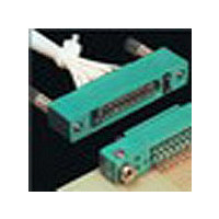
LOCKING SCREW ACCESSORY INSERTED INTO
large mounting holes at each end. The 0.126 inch diameter
IO CONNECTOR BODY
cross holes in the locking bushing must be aligned with the
0.126 inch diameter cross hole in the PC connector body.
These holes accept a 4–40 UNC-2A screw which should be
long enough to allow mounting to the board. Fasten with a
suitable washer and nut, making sure an appropriate washer
is also under the head.
The front of the locking bushing has a 4–40 UNC-2B THD
which will mate with the locking bushing accessory of an IO
connector.
MOTHER BOARD CONNECTOR
Locking/mounting bushing accessory 10-411196-3*, two per
connector, may be inserted into 0.185 inch diameter CSK
holes at each end of the front of a MB connector body. Using
a light arbor press or similar device, firmly press the knurled
section of the bushing into the lower 0.122 inch diameter hole
until the front of the bushing is flush with, or slightly below, the
front surface of the MB connector. Make sure the bushing and
hole axis are properly aligned. Avoid excessive force which
may crack the back surface of the MB connector body.
LOCKING BUSHING ACCESSORY INSERTED INTO
PC CONNECTOR BODY
The back of the locking/mounting bushing has a 4–40 UNC-
2A THD to mount the connector. Fasten the connector with a
suitable washer and nut.
The front of the locking/mounting bushing has a 4–40 UNC-
2B THD which will mate with the locking screw accessory of
an IO connector.
Alternate Mounting Variations for Mother Board Connector
1. A clinch nut (such as all ESNA 79NCFMA2-26 or equiva-
lent may be pressed from the front, knurled end first, through
the 0.185 diameter CSK into the 0.122 inch diameter hole at
each end of the connector. An appropriate length 2–56 UNC-
3A screw, washer, and nut may be used to mount the connec-
tor. Mounting forces should be applied to the bushing toward
the rear of the connector.
2. When a Daughter Board is mated use a 4–40 screw of
appropriate length, with a suitable washer under the head.
Insert the screw from the front of the connector through the
0.185 inch diameter CSK into the 0.122 inch diameter hole at
each end of the connector and fasten with a suitable washer
LOCKING/MOUNTING BUSHING ACCESSORY INSERTED
and nut.
INTO MB CONNECTOR BODY
For ordering information, see page 7.
29
**See L-1220 for additional information
Related parts for M55302/169C321
Image
Part Number
Description
Manufacturer
Datasheet
Request
R

Part Number:
Description:
Standard Card Edge Connectors DIN 96POS
Manufacturer:
AVX Corporation
Datasheet:
Part Number:
Description:
Connector,DIN-41612,PCB Mount,RECEPT,96 Contacts,PIN,0.1 Pitch,WRAP POST Terminal,HOLE .099-.111
Manufacturer:
AVX Corporation

Part Number:
Description:
Board to Board / Mezzanine Connectors POLARIZING KEY
Manufacturer:
Amphenol
Datasheet:
Part Number:
Description:
Cable Specification: PU CABLE, UL20549 24AWG*8C+AD,OD= 6.0mm
Manufacturer:
Amphenol