3-316080-3 TE Connectivity, 3-316080-3 Datasheet - Page 3
3-316080-3
Manufacturer Part Number
3-316080-3
Description
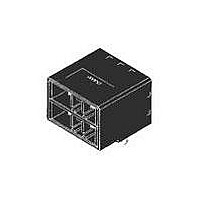
Headers & Wire Housings 10 POS HDR R/A 30 AU KEY XY
Manufacturer
TE Connectivity
Series
D3200M Seriesr
Specifications of 3-316080-3
Product Type
Headers - Shrouded
Connector Type
Header
Mount
Board Mount
Keyed
Yes
Product Series
D-3200M (Modular Type)
Pcb Mounting Orientation
Right Angle
Pcb Mount Style
Through Hole
Pcb Mount Retention
With
Keying
XY
Voltage Rating (vac)
600
Termination End Plating
Gold over Nickel
Number Of Positions
10
Number Of Rows
2
Centerline, Matrix (mm [in])
5.08 x 5.08 [.200 x .200]
Pcb Mount Retention Type
Boardlock(s)
Contact Type
Pin
Contact Plating, Mating Area, Material
Gold (30)
Contact Base Material
Copper Alloy
Connector Style
Plug
Housing Material
Thermoplastic - GF
Ul Flammability Rating
UL 94V-0
Housing Color
Black
Rohs/elv Compliance
RoHS compliant, ELV compliant
Lead Free Solder Processes
Wave solder capable to 240°C, Wave solder capable to 260°C, Wave solder capable to 265°C
Rohs/elv Compliance History
Converted to comply with RoHS directive
Applies To
Printed Circuit Board
Packaging Quantity
14
Packaging Method
Tube
Lead Free Status / Rohs Status
Details


3.5 性能必要条件と試験方法の要約
3.5 Test Requirements and Procedures Summary
3.5.0
3.5.0
3.5.1
3.5.1
3.5.2
3.5.2
3.5.3
3.5.3
3.5.4
3.5.4
Rev. J5
Para.
項目
製品の確認
Examination of Product
総合抵抗
(ローレベル)
Termination Resistance
(Low Level)
耐電圧
Dielectric withstanding
Voltage
絶縁抵抗
Insulation Resistance
温度上昇
Temperature Rising
Test Items
試験項目
製品図面とTE取付適用規格
114-5148 の必要条件に合致し
ていること。
Meets requirements of product
drawing and TE Specification
114- 5148
10 mΩ 以下(終期)
10 mΩ Max. (Final)
沿面放電、フラッシュオーバー
等がないこと。
リーク電流 0.5 mA 以下
3.81ピッチ:1.5kv AC
5.08ピッチ:2.2kv AC
No creeping discharge nor
flashover shall occur.
Current leakage :0.5 mA Max.
3.81 pitch:1.5kv AC
5.08 pitch:2.2kv AC
1000 MΩ 以上 (初期)
100 MΩ 以上(終期)
1000 MΩ Min.(Initial)
100 MΩ Min. (Final)
規定又は定格電流を通電して、
温度上昇は 30 °C 以下
30 °C Max. under loaded
specified current or rating
current.
5 mΩ 以下(初期)
5 mΩ Max. (Initial)
Electrical Requirements
Product Specification
Fig.3 (続く)(CONT.)
規
Requirements
電 気 的 性 能
格
製品規格
値
目視により、 コネクタの機能上支障をきた
す損傷を検査する。
Visual inspection
No physical damage
ハウジングに組み込まれ嵌合したコンタ
クトを開路電圧 50 mV 以下、
閉路電流 50 mA 以下の条件で測定する。
Fig. 4 参照。
EIA364-23A
Subject mated contacts assembled in
housing to 50 mV Max open circuit
at 50 mA Max closed circuit.
Fig. 4.
EIA364-23A
1 分間印加
コネクタ嵌合あり
隣接コンタクト間で測定。
EIA364-20
MIL-STD-202 試験法 301
1 minute.
Test between adjacent circuits of mated
connectors.
EIA364-20
MIL-STD-202 Method 301
500 V DC 印加。
コネクタ嵌合あり
隣接コンタクト間で測定。
EIA364-21
MIL-STD-202 試験法302 条件B
Impressed voltage 500 V DC.
Test between adjacent circuits of mated
connectors.
EIA364-21
MIL-STD-202 Method 302 Condition B
通電による温度上昇を測定すること。
Fig. 4 参照
EIA364-70
Measure temperature rising by energized
current.
EIA364-70
試
Fig.4
Procedures
験
方
法
108-5349
3 of 12
Related parts for 3-316080-3
Image
Part Number
Description
Manufacturer
Datasheet
Request
R

Part Number:
Description:
CONN HEADR BRKWAY .100 31POS STR
Manufacturer:
Tyco Electronics
Datasheet:
Part Number:
Description:
CONN HEADR BRKWAY .100 31POS STR
Manufacturer:
Tyco Electronics
Datasheet:
Part Number:
Description:
CONN HEADR BRKWAY .100 31POS STR
Manufacturer:
Tyco Electronics
Datasheet:
Part Number:
Description:
CONN HEADR BRKWAY .100 31POS STR
Manufacturer:
Tyco Electronics
Datasheet:
Part Number:
Description:
CONN HEADR BRKWAY .100 31POS STR
Manufacturer:
Tyco Electronics
Datasheet:

Part Number:
Description:
Manufacturer:
TE Connectivity
Datasheet:

Part Number:
Description:
Manufacturer:
TE Connectivity
Datasheet:

Part Number:
Description:
Manufacturer:
TE Connectivity
Datasheet:

Part Number:
Description:
Manufacturer:
TE Connectivity
Datasheet:

Part Number:
Description:
Manufacturer:
TE Connectivity
Datasheet:

Part Number:
Description:
Manufacturer:
TE Connectivity
Datasheet:

Part Number:
Description:
Conn IDC Connector F 3 POS 3.96mm IDT RA Cable Mount
Manufacturer:
TE Connectivity
Datasheet:
Part Number:
Description:
Conn IDC Connector F 3 POS 3.96mm IDT RA Cable Mount
Manufacturer:
TE Connectivity
Datasheet:

Part Number:
Description:
Conn IDC Connector F 3 POS 2.54mm IDT RA Cable Mount Loose Piece
Manufacturer:
TE Connectivity
Datasheet:
Part Number:
Description:
Conn IDC Connector F 3 POS 2.54mm IDT RA Cable Mount Loose Piece
Manufacturer:
TE Connectivity
Datasheet: