SW06BQ Analog Devices Inc, SW06BQ Datasheet - Page 10
SW06BQ
Manufacturer Part Number
SW06BQ
Description
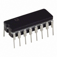
IC SWITCH QUAD SPST 16CDIP
Manufacturer
Analog Devices Inc
Datasheet
1.SW06GSZ-REEL.pdf
(12 pages)
Specifications of SW06BQ
Rohs Status
RoHS non-compliant
Function
Switch
Circuit
4 x SPST - NC/NO
On-state Resistance
80 Ohm
Operating Temperature
-40°C ~ 85°C
Mounting Type
Through Hole
Package / Case
16-CDIP (0.300", 7.62mm)
Available stocks
Company
Part Number
Manufacturer
Quantity
Price


SW06
APPLICATIONS INFORMATION
The single analog switch product configures, by appropriate pin
connections, into four switch applications. As shown in Figure
1, the SW06 connects as a QUAD SPST, a DUAL SPDT, a
DUAL DPST, or a DPDT analog switch. This versatility in-
creases further when taking advantage of the disable input (DIS)
which turns all switches OFF when taken active low.
Ion-implantation of the JFET analog switch achieves low ON
resistance and tight channel-to-channel matching. Combining
the low ON resistance and low leakage currents results in a
worst case voltage error figure V
R
ror is negligible considering dissimilar-metal thermally-induced
offsets will be in the 5 to 15 microvolt range.
LOGIC INPUTS
The logic inputs (IN
to a TTL logic threshold value of two forward diode drops (1.4 V
at +25 C) above the GND terminal. These inputs use PNP
transistors which draw maximum current at a logic “0” level and
drops to a leakage current of a reverse biased diode as the logic
input voltage raises above 1.4 volts. Any logic input voltage
greater than 2.0 volts becomes logic “1,” less than 0.8 volts be-
comes logic “0” resulting in full TTL noise immunity not avail-
able from similar CMOS input analog switches. The PNP
transistor inputs require such low input current that the SW06
approaches fan-ins of CMOS input devices. These bipolar logic
inputs exceed any CMOS input circuit in resistance to static
voltage and radiation susceptibility. No damage will occur to the
SW06 if logic high voltages are present when the SW06 power
SD(ON)
= 100 nA
100
X
) and disable input (DIS) are referenced
= 11 microvolts. This amount of er-
ERROR
@ +125 C = I
Figure 1. Functional Applications of SW06
D(ON)
–10–
supplies are OFF. When the V+ and V– supplies are OFF, the
logic inputs present a reverse bias diode loading to active logic
inputs. Input logic thresholds are independent of V+ and V–
supplies making single V+ supply operation possible by simply
connecting GND and V– together to the logic ground supply.
ANALOG VOLTAGE AND CURRENT
ANALOG VOLTAGE
These switches have constant ON resistance for analog voltages
from the negative power supply (V–) to within 4 volts of the
positive power supply. This characteristic shown in the plots re-
sults in good total harmonic distortion, especially when com-
pared to CMOS analog switches that have a 20 to 30 percent
variation in ON resistance versus analog voltage. Positive analog
input voltage should be restricted to 4 volts less than V+ assur-
ing the switch remains open circuit in the OFF state. No in-
crease in switch ON resistance occurs when operating at supply
voltages less than 15 volts (see plot). Small signals have a 3 dB
down frequency of 70 MHz (see insertion loss versus frequency
plot).
ANALOG CURRENT
The analog switches in the ON state are JFETs biased in their
triode region and act as switches for analog current up to the I
specification (see plot of I
pulsed currents exceeding the I
tor reset switch discharging a shunt capacitor will produce a
peak current of I
best to connect the source to the most positive end of the ca-
pacitor, thereby achieving the lowest switch resistance and
A(PEAK)
= V
DS
CAP
vs V
A
/R
DS
spec. For example, an integra-
DS(ON)
). Some applications require
. In this application, it is
REV. A
A
Related parts for SW06BQ
Image
Part Number
Description
Manufacturer
Datasheet
Request
R

Part Number:
Description:
±1.7g Dual-Axis IMEMS Accelerometer Evaluation Board
Manufacturer:
Analog Devices Inc
Datasheet:

Part Number:
Description:
Inertial Sensor Evaluation System
Manufacturer:
Analog Devices Inc
Datasheet:
Part Number:
Description:
Manufacturer:
Analog Devices Inc
Datasheet:
Part Number:
Description:
Manufacturer:
Analog Devices Inc
Datasheet:
Part Number:
Description:
Manufacturer:
Analog Devices Inc
Datasheet:
Part Number:
Description:
Manufacturer:
Analog Devices Inc
Datasheet:
Part Number:
Description:
Manufacturer:
Analog Devices Inc
Datasheet:
Part Number:
Description:
Manufacturer:
Analog Devices Inc
Datasheet:
Part Number:
Description:
Manufacturer:
Analog Devices Inc
Datasheet:
Part Number:
Description:
Manufacturer:
Analog Devices Inc
Datasheet:
Part Number:
Description:
Manufacturer:
Analog Devices Inc
Datasheet:
Part Number:
Description:
Manufacturer:
Analog Devices Inc
Datasheet:
Part Number:
Description:
Manufacturer:
Analog Devices Inc
Datasheet: