TDA2050V STMicroelectronics, TDA2050V Datasheet
TDA2050V
Specifications of TDA2050V
Available stocks


Related parts for TDA2050V


TDA2050V Summary of contents
Page 1
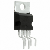
... The high power and very low harmonic and cross- over distortion (THD = 0.05% typ 22V 1KHz 0.1 to 15W make the device most suitable for both HiFi and = S high class TV sets. TDA2050 Pentawatt ORDERING NUMBERS: TDA2050V TDA2050H =8ohm 100Hz to 15KHz 22V, S 1/13 ...
Page 2
TDA2050 ABSOLUTE MAXIMUM RATINGS Symbol V Supply Voltage S V Input Voltage i V Differential Input Voltage i I Output Peak Current (internally limited Power Dissipation T tot CASE Storage and Junction Temperature stg j ...
Page 3
ELECTRICAL CHARACTERISTICS (Refer to the Test Circuit, V less otherwise specified) Symbol Parameter V Supply Voltage Range S I Quiescent Drain Current d I Input Bias Current b V Input Offset Voltage OS I Input Offset Current OS P RMS ...
Page 4
TDA2050 Figure 1: Split Supply Typical Application Circuit Figure 2: P.C. Board and Components Layout of the Circuit of Fig. 1 (1:1) Vi 4/13 TDA2050 + -Vs ...
Page 5
SPLIT SUPPLY APPLICATION SUGGESTIONS The recommended values of the external compo- nents are those shown on the application circuit Recommended Component Value R1 22k Input Impedance R2 680 Feedback Resistor R3 22k R4 2.2 Frequency Stability Input ...
Page 6
TDA2050 Figure 3: Single Supply Typical Application Circuit Figure 4: P.C. Board and Components Layout of the Circuit of Fig. 3 (1:1) 6/13 ...
Page 7
SINGLE SUPPLY APPLICATION SUGGESTIONS The recommended values of the external compo- nents are those shown on the application circuit Recommended Component Value R1, R2, R3 22k Biasing Resistor R4 680 Feedback Resistors R5 22k R6 2.2 Frequency Stability C1 2.2 ...
Page 8
TDA2050 Figure 7: Output Power vs. Supply Voltage Figure. 9: Distortion vs. Frequency Figure 11: Quiescent Current vs. Supply Voltage 8/13 Figure 8: Distortion vs. Output Power Figure 10: Distortion vs. Frequency Figure 12: Supply Voltage Rejection vs. Frequency ...
Page 9
Figure 13: Supply Voltage Rejection vs. Fre- quency (Single supply) for Different values of C2 (circuit of fig. 3) Figure 14: Supply Voltage Rejection vs. Fre- quency (Single supply) for Different values of C2 (circuit of fig. 3) Figure 15: ...
Page 10
TDA2050 ent. Fig. 17 shows this dissipable power as a function of ambient temperature for different ther- mal resistance. Figure 17: Maximum Allowable Power Dissipa- tion vs. Ambient Temperature MOUNTING INSTRUCTIONS The power dissipated in the circuit must be re- ...
Page 11
A circuit for generating the test signal is given in fig. 19. The load network consists capacitor, in series with a 1 ohm resistor. The capacitor limits the current due to the 20 Hz signal to ...
Page 12
TDA2050 mm DIM. MIN. TYP. MAX. A 4.8 C 1.37 D 2.4 2.8 0.094 D1 1.2 1.35 0.047 E 0.35 0.55 0.014 E1 0.76 1.19 0.030 F 0.8 1.05 0.031 F1 1.0 1.4 0.039 G 3.2 3.4 3.6 0.126 G1 ...
Page 13
... This publication supersedes and replaces all information previously supplied. STMicroelectronics products are not authorized for use as critical components in life support devices or systems without express written approval of STMicroelectronics. © 2002 STMicroelectronics – Printed in Italy – All Rights Reserved PENTAWATT® ...