TDA2040V STMicroelectronics, TDA2040V Datasheet
TDA2040V
Specifications of TDA2040V
Available stocks


Related parts for TDA2040V


TDA2040V Summary of contents
Page 1
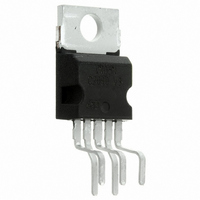
... A thermal shut-down system is also included. Table 1. Device summary Order code TDA2040V Doc ID 1460 Rev 4 TDA2040 Pentawatt V Package Pentawatt V (vertical) 1/16 www.st.com ...
Page 2
Pin connections 1 Pin connections Figure 2. Schematic diagram Figure 3. Pin connections 2/16 Doc ID 1460 Rev 4 TDA2040 ...
Page 3
TDA2040 2 Electrical specifications 2.1 Absolute maximum ratings Table 2. Absolute maximum ratings Symbol Vs Supply voltage Vi Input voltage Vi Differential input voltage Io Output peak current (internally limited) P Power dissipation at Tcase = 75 °C tot T ...
Page 4
Electrical specifications Table 4. Electrical characteristics (continued) Symbol P Output power o BW Power bandwidth G Voltage gain (open loop) vOL G Voltage gain (closed loop kHz v d Total harmonic distortion e Input noise voltage N ...
Page 5
TDA2040 2.4 Characterizations Figure 4. Output power vs supply voltage Figure 6. Output power vs supply voltage Figure 8. SVRR vs frequency Figure 5. Output power vs supply voltage Figure 7. Distortion vs frequency Figure 9. SVRR vs voltage gain ...
Page 6
Electrical specifications Figure 10. Quiescent drain current vs supply voltage Figure 12. Power dissipation vs output power 6/16 Figure 11. Open loop gain vs frequency Doc ID 1460 Rev 4 TDA2040 ...
Page 7
TDA2040 3 Applications 3.1 Circuits and PCB layouts Figure 13. Amplifier with split power supply Figure 14. PCB and components layout for the circuit of Doc ID 1460 Rev 4 Applications Figure 13 7/16 ...
Page 8
Applications Figure 15. Amplifier with single power supply Note : In this case of highly inductive loads protection diodes may be necessary. Figure 16. PCB and components layout for the circuit of 8/16 Doc ID 1460 Rev 4 TDA2040 Figure ...
Page 9
TDA2040 Figure 17. 30-watt bridge amplifier with split power supply Figure 18. PCB and components layout for the circuit of Doc ID 1460 Rev 4 Applications Figure 17 9/16 ...
Page 10
Applications Figure 19. Two-way hi-fi system with active crossover Figure 20. PCB and components layout for the circuit of 10/16 Doc ID 1460 Rev 4 TDA2040 Figure 19 ...
Page 11
TDA2040 3.2 Multiway speaker systems and active boxes Multiway loudspeaker systems provide the best possible acoustic performance since each loudspeaker is specially designed and optimized to handle a limited range of frequencies. Commonly, these loudspeaker systems divide the audio spectrum ...
Page 12
... Applications Figure 23. Active power filter A more effective solution, named "Active Power Filter" by STMicroelectronics, is shown in Figure 23. The proposed circuit can be realized by combined power amplifiers and 12-dB/octave or 18-dB/octave high-pass or low-pass filters. The component values calculated for fc = 900Hz using a Bessel 3rd order Sallen and Key ...
Page 13
TDA2040 3.3 Pratical consideration 3.3.1 Printed circuit board The layout shown in Figure 14 should be adopted by the designers. If different layouts are used, the ground points of input 1 and input 2 must be well decoupled from the ...
Page 14
Package mechanical data 4 Package mechanical data Figure 25. Pentawatt V outline drawing DIM L10 ...
Page 15
TDA2040 5 Revision history Table 6. Document revision history Date Apr-2003 28-Oct-2010 Revision 3 Changes not recorded Added features list on page 1 Updated minimum supply voltage to ±4 Corrected the title of Updated presentation Doc ID ...
Page 16
... Information in this document is provided solely in connection with ST products. STMicroelectronics NV and its subsidiaries (“ST”) reserve the right to make changes, corrections, modifications or improvements, to this document, and the products and services described herein at any time, without notice. All ST products are sold pursuant to ST’s terms and conditions of sale. ...