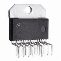
LM4730TA/NOPB National Semiconductor, LM4730TA/NOPB Datasheet

LM4730TA/NOPB
Specifications of LM4730TA/NOPB
LM4730TA
Related parts for LM4730TA/NOPB
LM4730TA/NOPB Summary of contents
Page 1
... Connection Diagrams (Note Plastic Package Top View Non-Isolated Package Order Number LM4730TA See NS Package Number TA15A © 2009 National Semiconductor Corporation 200594 Version 3 Revision 2 LM4730 Key Specifications ■ Output power into 4Ω or 8Ω, 10% THD+N ■ THD+N at 1kHz with into 8Ω ...
Page 2
Typical Application www.national.com FIGURE 1. Typical Audio Amplifier Application Circuit 2 200594 Version 3 Revision 2 Print Date/Time: 2009/10/26 15:41:58 20059453 ...
Page 3
... Absolute Maximum Ratings 2) If Military/Aerospace specified devices are required, please contact the National Semiconductor Sales Office/ Distributors for availability and specifications. Supply Voltage | Common Mode Input Voltage Differential Input Voltage Output Current Power Dissipation (Note 3) ESD Susceptability (Note 4) ESD Susceptability (Note ...
Page 4
Symbol Parameter Mute V Mute Low Input Voltage IL V Mute High Input Voltage IH Note 1: All voltages are measured with respect to the ground pin, unless otherwise specified. Note 2: Absolute Maximum Ratings indicate limits beyond which damage ...
Page 5
Bridged Amplifier Application Circuit FIGURE 2. Bridged Amplifier Application Circuit 200594 Version 3 Revision 2 5 Print Date/Time: 2009/10/26 15:41:58 20059405 www.national.com ...
Page 6
Single Supply Application Circuit Note: *Optional components dependent upon specific design requirements. Auxiliary Amplifier Application Circuit www.national.com FIGURE 3. Single Supply Amplifier Application Circuit FIGURE 4. Special Audio Amplifier Application Circuit 6 200594 Version 3 Revision 2 Print Date/Time: 2009/10/26 ...
Page 7
External Components Description ( See Figures Components 1 R Prevents currents from entering the amplifier's non-inverting input which may be passed through to the load B upon power down of the system due to the low ...
Page 8
Typical Performance Characteristics Supply Current vs Supply Voltage THD+N vs Frequency ±14V 1W/Channel 4Ω, 80kHz www.national.com 20059467 20059468 8 200594 Version 3 Revision 2 Print Date/Time: 2009/10/26 15:41:58 PSRR vs Frequency ±17V, V ...
Page 9
THD+N vs Output Power = 4Ω, 80kHz BW ±14V 20059470 Output Power vs Supply Voltage = 4Ω, 80kHz 1kHz 20059462 200594 Version 3 Revision 2 THD+N vs Output Power = 8Ω, 80kHz BW ...
Page 10
Power Dissipation vs Output Power = 4Ω, 80kHz BW 1% THD (max Crosstalk vs Frequency ±14V 10W 4Ω, 80kHz www.national.com 20059460 20059472 10 200594 Version 3 Revision 2 Print Date/Time: 2009/10/26 ...
Page 11
Mute Attenuation vs Mute Pin Voltage ±17V 1W 8Ω, 80kHz 20059459 Supply Current vs Standby Pin Voltage ±17V 20059466 200594 Version 3 Revision 2 Standby Attenuation vs Standby Pin Voltage ±17V ...
Page 12
Application Information MUTE MODE By placing a logic-high voltage on the mute pins, the signal going into the amplifiers will be muted. If the mute pins are left floating or connected to a logic-low voltage, the amplifiers will be in ...
Page 13
If adequate bypassing is not provided, the current in the sup- ply leads which is a rectified component of the load current ...
Page 14
To achieve a transient free power-up and power-down, the voltage seen at the input terminals should be ideally the same. Such a signal will be common-mode in nature, and will be rejected by the LM4730. In Figure 3, the resistor ...
Page 15
FIGURE 6. Reference PCB Schematic 15 200594 Version 3 Revision 2 Print Date/Time: 2009/10/26 15:41:58 20059458 www.national.com ...
Page 16
LM4730 REFERENCE BOARD ARTWORK Composite View Top Layer www.national.com 20059454 20059456 16 200594 Version 3 Revision 2 Print Date/Time: 2009/10/26 15:41:58 Silk Screen 20059455 Bottom Layer 20059457 ...
Page 17
BILL OF MATERIALS FOR REFERENCE PCB Symbol Value Toleranc 47kΩ IN1 IN2 1kΩ 20kΩ 1kΩ 4.7Ω R ...
Page 18
Physical Dimensions www.national.com inches (millimeters) unless otherwise noted Non-Isolated TO-220 15-Lead Package Order Number LM4730TA NS Package Number TA15A 18 200594 Version 3 Revision 2 Print Date/Time: 2009/10/26 15:41:58 ...
Page 19
Notes 19 200594 Version 3 Revision 2 Print Date/Time: 2009/10/26 15:41:58 www.national.com ...
Page 20
... For more National Semiconductor product information and proven design tools, visit the following Web sites at: Products Amplifiers www.national.com/amplifiers Audio www.national.com/audio Clock and Timing www.national.com/timing Data Converters www.national.com/adc Interface www.national.com/interface LVDS www.national.com/lvds Power Management www.national.com/power Switching Regulators www.national.com/switchers LDOs www.national.com/ldo LED Lighting www ...


