ZBZ1604 Crouzet USA, ZBZ1604 Datasheet - Page 173
ZBZ1604
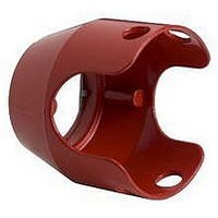
Manufacturer Part Number
ZBZ1604
Description
17C8378
Manufacturer
Crouzet USA
Datasheet
1.ZBZ1604.pdf
(240 pages)
Specifications of ZBZ1604
Features
Red, Metal
Rohs Compliant
Yes
For Use With
40mm Emergency Stop And Mushroom Head Pushbuttons


In hazardous locations, it is not always required to use explo-
sion-proof equipment like the Class 9001 Type BR control sta-
tions. It can save money to know what type of hazardous
location exists. If you're not sure what type of hazardous loca-
tion exists, the “Summary of Classification” Chart may help. If
not, contact your local electrical inspector. When you know
what class, division, and group(s) exists, see the table in the
lower left hand corner of this page for what Square D has to of-
fer
Summary Of Classification Chart
✻ An intrinsically safe system requires either a Class 8501 Type TO or NY2 barrier relay or an in-
◆ Any Class 9001 Type K, SK or KX operator can be used in an area classified as Class I,
▲ Any Class 9001 Type K, SK, or KX operator mounted in a Class 9001 Type KY, KYSS, KYAF,
For ◆ and ▲: UL Listed: File E10054, CCN NOIV.
For ■: Add Form Y243 to single lamp Push To Test pilot lights.
04/2005
III. Fibers
I. Gas
II. Dust
Class
trinsically safe barrier to restrict the energy available in the area classified as a hazardous area
to a level less than that required to cause an explosion. In an intrinsically safe system, any non-
illuminated Class 9001 operator or control station with standard contacts can be used. No illu-
minated operators, except the Class 9001 Type KP44 intrinsically safe pilot light, may be used.
Division 2 hazardous locations.
1.Only logic (KA40 series) or power (KA50 series) reed contact blocks are used.
2.All Type K and SK illuminated operators are UL approved for use in Class I Division 2 areas. ■
3.Type KX illuminated operators do not use 4 lamp light modules, or 2 lamp light modules
other than the transformer type. ■
4.The operators are mounted in Type KY, KYSS, KYAF, SKY enclosures.
SKY enclosure may be used, except potentiometer operators.
.
III
II
II
II
I
I
I
I
Class
Division
1, 2
1
1
2
2
1
2
2
For
1. Hazard May Exist
2. Potential Hazard
1. Hazard May Exist
2. Potential Hazard
1. Production Areas
2. Handling and
Group(s)
B, C, D
B, C, D
E, F, G
E, F
....
May Exist In Atmos-
phere Under Normal
Operating Conditions.
A. May be present in
B. Location adjacent
May Exist In Atmos-
phere Under Normal
Operating Conditions.
A. May be present in
Storage Areas
G
A
A
atmosphere only
under abnormal
circumstances.
to Division 1
location.
atmosphere only
under abnormal
circumstances.
Reed Contact Blocks & Hazardous Location Information - Type K, SK, KX, and T
Division
1. Intrinsically Safe System✻
1.
2.
1.
2.
1.
2.
3.
1.
2.
1.
2.
3.
1.
2.
3.
1.
2.
3.
9001 BR station
Intrinsically Safe System✻
9001 K, SK, KX control stations with the
restrictions listed in footnote◆
Intrinsically Safe System✻
9001 BR station
9001 K, SK, KX control stations with the
restrictions listed in footnote◆
Intrinsically Safe System✻
9001 BR station
Intrinsically Safe System✻
9001 BR station
9001 K, SK, KX control stations with the
restrictions listed in footnote◆
Intrinsically Safe System✻
9001 BR station
9001 K, SK, KX control stations with the
restrictions listed in footnote▲
Intrinsically Safe System✻
9001 BR Station
9001 K, SK, KX control stations with the
restrictions listed in footnote▲
Intrinsically Safe System✻
A. Acetylene
B. Hydrogen and Manufactured Gases
C. Petrochemicals (e.g. ethylene)
D. Petrochemicals (e.g. alcohol)
A. Acetylene
B. Hydrogen and Manufactured Gases
C. Petrochemicals (e.g. ethylene)
D. Petrochemicals (e.g. alcohol)
E. Conductive and Combustible Dust
G. Non-Conductive Combustible Dust
G. Non-Conductive Combustible Dust
F. Carbonaceous Dusts (Resistivity
containing Hydrogen
Containing Hydrogen
(Resistivity <10
>10
(Resistivity > = 10
(Resistivity > = 10
Easily Ignitable Fibers or Flyings
Easily Ignitable Fibers or Flyings
2
ohm/cm but ð10
Use
Group
5
ohms/cm)
5
5
ohms/cm)
ohms/cm)
Push Button and Operator Interface - Type KX 30 mm
8
ohm/cm)
All contact blocks listed below will accept #12-18 solid or stranded wire.
Hermetically Sealed Logic Reed Contact Blocks
Suitable for use on low energy level circuits
The maximum number of logic and/or power reed contact blocks per operator is
as indicated for standard contact blocks, except:
• On 3 position selector switches with cams “C,” “D,” “E,” “F,” “G,” “L,” or “M,”
• On 4 position selector switches, mount reed blocks on one side only (either
Hermetically Sealed Power Reed Contact Blocks
The power reed contact blocks can be used with standard industrial relays and starters through
NEMA Size 4. Minimum voltage is 5 volts and the minimum current is 1 mA.
①
Inductive Rating – 35% Power Factor.
mount reed blocks on one side only (either side), maximum 2 in tandem.
side), maximum 2 in tandem.
Volts
Volts
120
240
115
Description
Max. Volts AC/DC
Description
© 1999-2005 Schneider Electric All Rights Reserved
120/100
32/30
Amps
Amps
10.00
0.50
5.00
Make
Make
1200
1200
VA
VA
58
AC NEMA / UL Type C300
DC NEMA / UL Type Q150
Amps
Amps
1.000
0.500
0.50
➁
Symbol
Inductive and Resistive Ratings
0.25A
Res.
8 VA
Break
Break
Symbol
Maximum Load
120
120
VA
VA
58
①
0.10A
3 VA
Ind.
Carrying Amps
Carrying Amps
Continuous
Continuous
KA51
KA52
KA53
KA54
KA55
Type
Type
KA41
KA42
KA43
KA44
KA45
3.0
3.0
3.0
Cont.
0.5 A
0.5 A
173
Related parts for ZBZ1604
Image
Part Number
Description
Manufacturer
Datasheet
Request
R

Part Number:
Description:
SCREW SOCKET (OT08PC)
Manufacturer:
Crouzet USA
Datasheet:

Part Number:
Description:
PANEL PLATE FOR 813
Manufacturer:
Crouzet USA
Datasheet:
Part Number:
Description:
Controller; CTD46 Dual Display Temperature, 1/16 DIN, NEMA 4X, 110/220VAC
Manufacturer:
Crouzet USA
Datasheet:

Part Number:
Description:
11R1084
Manufacturer:
Crouzet USA
Datasheet:
Part Number:
Description:
11R1086
Manufacturer:
Crouzet USA
Datasheet:
Part Number:
Description:
11R1087
Manufacturer:
Crouzet USA
Datasheet:
Part Number:
Description:
11R1089
Manufacturer:
Crouzet USA
Datasheet:
Part Number:
Description:
11R1078
Manufacturer:
Crouzet USA
Datasheet:
Part Number:
Description:
11R1079
Manufacturer:
Crouzet USA
Datasheet: