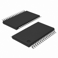
TDA8932BTW/N2,112 NXP Semiconductors, TDA8932BTW/N2,112 Datasheet - Page 4

TDA8932BTW/N2,112
Manufacturer Part Number
TDA8932BTW/N2,112
Description
IC AMP AUDIO 55W STER D 32TSSOP
Manufacturer
NXP Semiconductors
Type
Class Dr
Datasheet
1.TDA8932BTWN2118.pdf
(48 pages)
Specifications of TDA8932BTW/N2,112
Package / Case
32-TSSOP Exposed Pad, 32-eTSSOP, 32-HTSSOP
Output Type
1-Channel (Mono) or 2-Channel (Stereo)
Max Output Power X Channels @ Load
55W x 1 @ 8 Ohm; 26.5W x 2 @ 4 Ohm
Voltage - Supply
10 V ~ 36 V, ±5 V ~ 18 V
Features
Depop, Differential Inputs, Mute, Short-Circuit and Thermal Protection
Mounting Type
Surface Mount
Mounting Style
SMD/SMT
Lead Free Status / RoHS Status
Lead free / RoHS Compliant
Other names
935283479112
TDA8932BTW
TDA8932BTW
TDA8932BTW/N2
TDA8932BTW/N2
TDA8932BTW
TDA8932BTW
TDA8932BTW/N2
TDA8932BTW/N2
NXP Semiconductors
7. Pinning information
TDA8932B_4
Product data sheet
Fig 2.
POWERUP
Pin configuration SO32
V
V
ENGAGE
OSCREF
HVPREF
SSD(HW)
SSD(HW)
CGND
INREF
TEST
DIAG
V
V
IN1N
IN2N
IN1P
IN2P
DDA
SSA
7.1 Pinning
7.2 Pin description
10
11
12
13
14
15
16
1
2
3
4
5
6
7
8
9
Table 3.
Symbol
V
IN1P
IN1N
DIAG
ENGAGE
POWERUP
CGND
V
V
OSCREF
HVPREF
INREF
TEST
IN2N
IN2P
V
V
DREF
TDA8932BT
SSD(HW)
DDA
SSA
SSD(HW)
SSD(HW)
001aaf598
Pin description
Pin
1
2
3
4
5
6
7
8
9
10
11
12
13
14
15
16
17
18
32
31
30
29
28
27
26
25
24
23
22
21
20
19
18
17
V
OSCIO
HVP1
V
BOOT1
OUT1
V
STAB1
STAB2
V
OUT2
BOOT2
V
HVP2
DREF
V
SSD(HW)
DDP1
SSP1
SSP2
DDP2
SSD(HW)
Rev. 04 — 18 December 2008
Description
negative digital supply voltage and handle wafer connection
positive audio input for channel 1
negative audio input for channel 1
diagnostic output; open-drain
engage input to switch between Mute mode and Operating mode
power-up input to switch between Sleep mode and Mute mode
control ground; reference for POWERUP, ENGAGE and DIAG
positive analog supply voltage
negative analog supply voltage
input internal oscillator setting (only master setting)
decoupling of internal half supply voltage reference
decoupling for input reference voltage
test signal input; for testing purpose only
negative audio input for channel 2
positive audio input for channel 2
negative digital supply voltage and handle wafer connection
negative digital supply voltage and handle wafer connection
decoupling of internal (reference) 5 V regulator for logic supply
Fig 3.
POWERUP
V
V
ENGAGE
OSCREF
HVPREF
SSD(HW)
SSD(HW)
INREF
CGND
TEST
DIAG
V
V
IN1N
IN2N
IN1P
IN2P
DDA
Pin configuration HTSSOP32
SSA
10
11
12
13
14
15
16
1
2
3
4
5
6
7
8
9
TDA8932BTW
Class-D audio amplifier
TDA8932B
001aaf599
© NXP B.V. 2008. All rights reserved.
32
31
30
29
28
27
26
25
24
23
22
21
20
19
18
17
V
OSCIO
HVP1
V
BOOT1
OUT1
V
STAB1
STAB2
V
OUT2
BOOT2
V
HVP2
DREF
V
SSD(HW)
DDP1
SSP1
SSP2
DDP2
SSD(HW)
4 of 48


