TDA7563AH STMicroelectronics, TDA7563AH Datasheet
TDA7563AH
Specifications of TDA7563AH
Available stocks


Related parts for TDA7563AH


TDA7563AH Summary of contents
Page 1
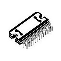
... Standby/mute pin ■ Linear thermal shutdown with multiple thermal warning ■ ESD protection Table 1. Device summary Order code TDA7563A TDA7563AH TDA7563ASM TDA7563ASMTR TDA7563APD February 2008 4 x 50W multifunction quad power amplifier with built-in diagnostics feature PowerSO36 (Slug up) Flexiwatt27 (Vertical) Description The TDA7563A is a new BCD technology Quad Bridge type of car radio amplifier in Flexiwatt27 & ...
Page 2
Contents Contents 1 Block, pins connection and application diagrams . . . . . . . . . . . . . . . . . 5 2 Electrical specifications . . . . . . . . . . ...
Page 3
TDA7563A List of tables Table 1. Device summary . . . . . . . . . . . . . . . . . . . . . . . . . . . . . . . . ...
Page 4
List of figures List of figures Figure 1. Block diagram . . . . . . . . . . . . . . . . . . . . . . . . . . . . . . ...
Page 5
TDA7563A 1 Block, pins connection and application diagrams Figure 1. Block diagram ST-BY/MUTE Figure 2. Application circuit BUS Block, pins connection ...
Page 6
Block, pins connection and application diagrams Figure 3. Pin connections - Flexiwatt27 (Top view) Flexiwatt 27 (horizontal/SMD) Figure 4. Pin connections - PowerSO36 (Top view) 6/35 27 TAB 26 DATA 25 PW_GND RR 24 OUT RR OUT RR+ ...
Page 7
TDA7563A 2 Electrical specifications 2.1 Absolute maximum ratings Table 1. Absolute maximum ratings Symbol V Operating supply voltage supply voltage S V Peak supply voltage (for t = 50ms) peak V CK pin voltage CK V Data ...
Page 8
Electrical specifications Table 3. Electrical characteristics (continued) (Refer to the test circuit, V Symbol Parameter THD Total harmonic distortion C Cross talk T R Input impedance IN G Voltage gain 1 (default) V1 ΔG Voltage gain match ...
Page 9
TDA7563A Table 3. Electrical characteristics (continued) (Refer to the test circuit, V Symbol Parameter CD Clip det. THD level THD Turn on diagnostics 1 (Power amplifier mode) Short to GND det. (below this Pgnd limit, the output is considered in ...
Page 10
Electrical specifications Table 3. Electrical characteristics (continued) (Refer to the test circuit, V Symbol Parameter V Offset detection O I Normal load current detection NL I Open load current detection bus interface S Clock frequency CL ...
Page 11
TDA7563A Figure 9. Distortion vs. output power (4Ω, HI- EFF) THD (%) EFF MODE Ω KHz 0 KHz 0.01 0.001 0.1 ...
Page 12
Electrical specifications Figure 15. Power dissipation and efficiency vs. output power (4Ω, STD, SINE) Ptot (W) 90 STANDARD MODE 14 Ohm KHz SINE ...
Page 13
TDA7563A 3 Diagnostics functional description 3.1 Turn-on diagnostic It is activated at the turn-on (standby out) under I are: – SHORT TO GND – SHORT TO Vs – SHORT ACROSS THE SPEAKER – OPEN SPEAKER To verify if any of ...
Page 14
Diagnostics functional description Figure 20. SVR and output behavior (case 1: without turn-on diagnostic) Vsvr Out Bias (power amp turn-on) I2CB DATA Figure 21. SVR and output pin behavior (case 2: with turn-on diagnostic) Vsvr Out Diagnostic Enable (Turn-on) I2CB ...
Page 15
TDA7563A Concerning SHORT ACROSS THE SPEAKER / OPEN SPEAKER, the threshold varies from gain setting, since different loads are expected (either normal speaker's impedance or high impedance). The values in case gain ...
Page 16
Diagnostics functional description radio operating time. – To check the status of the device a sampling system is needed. The timing is chosen at microprocessor level (over half a second is recommended). Figure 25. Restart timing ...
Page 17
TDA7563A 4 Output DC offset detection Any DC output offset exceeding +/- 2 V are signalled out. This inconvenient might occur as a consequence of initially defective or aged and worn-out input capacitors feeding a DC component to the inputs, ...
Page 18
Output DC offset detection Figure 27. Current detection: Load impedance |Z| vs. output peak voltage Load |z| (Ohm 4.2 Multiple faults When more misconnections are simultaneously in place at the audio ...
Page 19
TDA7563A 4.3 Faults availability All the results coming from I measurements inside a defined period of time. If the fault is stable throughout the whole period, it will be sent out. To guarantee always resident functions, every kind of diagnostic ...
Page 20
Thermal protection 5 Thermal protection Thermal protection is implemented through thermal foldback Thermal foldback begins limiting the audio input to the amplifier stage as the junction temperatures rise above the normal operating range. This effectively limits the output power capability ...
Page 21
TDA7563A 6 Fast muting The muting time can be shortened to less than 1.5ms by setting (IB2 This option can be useful in transient battery situations (i.e. during car engine cranking) to quickly turnoff the amplifier for ...
Page 22
I2C bus bus 2 7 programming/reading sequences A correct turn on/off sequence respectful of the diagnostic timings and producing no audible noises could be as follows (after battery connection): TURN-ON: PIN2 > 7V --- ...
Page 23
TDA7563A 7.6 Acknowledge (*) The transmitter pulse (see Figure line during the acknowledge clock pulse, so that the SDA line is stable LOW during this clock pulse. (*) Transmitter – master (µP) when it writes an address to the TDA7563A ...
Page 24
Software specifications 8 Software specifications All the functions of the TDA7563A are activated by I The bit 0 of the "ADDRESS BYTE" defines if the next bytes are write instruction (from μP to TDA7563A) or read instruction (from TDA7563A to ...
Page 25
TDA7563A Table 7. IB2 Normal muting time ( Fast muting time ( Standby on - Amplifier not working - ( Standby off - Amplifier working - (D4 = ...
Page 26
Software specifications Table 9. DB2 Offset detection not activated ( Offset detection activated ( Channel LR Current Detection D5 Output peak current <250mA - Output load ( Output peak current >500mA ...
Page 27
TDA7563A Table 10. DB3 D7 Standby status (= IB2 - D4) D6 Diagnostic status (= IB1 - D6) Channel RF Current Detection D5 Output peak current <250mA - Output load ( Output peak current >500mA - Output load ...
Page 28
Software specifications Table 11. DB4 D7 Thermal warning 2 active ( Thermal warning 3 active (D6 = 1), T Channel RR Current Detection D5 Output peak current <250mA - Output load ( Output peak ...
Page 29
TDA7563A 9 Examples of bytes sequence 1 - Turn-On diagnostic - Write operation Start Address byte with Turn-On diagnostic - Read operation Start Address byte with ● The delay from 1 to ...
Page 30
Package information 10 Package information In order to meet environmental requirements, ST (also) offers these devices in ECOPACK packages. ECOPACK is marked on the package and on the inner box label, in compliance with JEDEC Standard JESD97. The maximum ratings ...
Page 31
TDA7563A Figure 33. Flexiwatt27 (SMD) mechanical data and package dimensions DIM. MIN. A 4. 0.36 F** 0.47 G(*) 0.75 G1 25.70 G2(*) 1.75 H(**) 28. L(**) 15.50 L1 7.70 L2 14.00 L3 ...
Page 32
Package information Figure 34. Flexiwatt27 (vertical) mechanical data and package dimensions DIM. MIN. A 4. 0.75 E 0.37 F (1) G 0.80 G1 25.75 H (2) 28. (2) 22.07 L1 18.57 L2 ...
Page 33
TDA7563A Figure 35. Flexiwatt27 (horizontal) mechanical data and package dimensions DIM. MIN. A 4. 0.37 F (1) G 0.80 G1 25.75 H (2) 28. (2) 21.64 L1 10.15 L2 (2) 15.50 ...
Page 34
Revision history 11 Revision history Table 12. Document revision history Date 07-Feb-2008 34/35 Revision 1 Initial release. TDA7563A Changes ...
Page 35
... TDA7563A Information in this document is provided solely in connection with ST products. STMicroelectronics NV and its subsidiaries (“ST”) reserve the right to make changes, corrections, modifications or improvements, to this document, and the products and services described herein at any time, without notice. All ST products are sold pursuant to ST’s terms and conditions of sale. ...