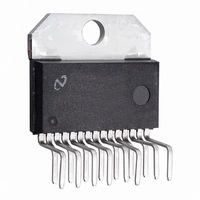
LM1876T/NOPB National Semiconductor, LM1876T/NOPB Datasheet

LM1876T/NOPB
Specifications of LM1876T/NOPB
*LM1876T/NOPB
LM1876T
Available stocks
Related parts for LM1876T/NOPB
LM1876T/NOPB Summary of contents
Page 1
... Connection Diagram SPiKe ™ Protection and Overture ™ are trademarks of National Semiconductor Corporation. © 2003 National Semiconductor Corporation Audio Power Amplifier Series Key Specifications j THD+N at 1kHz 15W continuous average output power into 4Ω or 8Ω: ...
Page 2
Typical Application FIGURE 1. Typical Audio Amplifier Application Circuit Note: Numbers in parentheses represent pinout for amplifier B. www.national.com 01207201 * Optional component dependent upon specific design requirements. 2 ...
Page 3
... Absolute Maximum Ratings 5) If Military/Aerospace specified devices are required, please contact the National Semiconductor Sales Office/ Distributors for availability and specifications. Supply Voltage | (No Input) Supply Voltage | (with Input) Common Mode Input Voltage Differential Input Voltage Output Current Power Dissipation (Note 6) ESD Susceptability (Note 7) ...
Page 4
Electrical Characteristics The following specifications apply for V 25˚C. Symbol Parameter CMRR Common Mode Rejection Ratio (Note 2) A Open Loop Voltage Gain VOL (Note 2) GBWP Gain Bandwidth Product e Input Noise IN (Note 3) SNR Signal-to-Noise Ratio A ...
Page 5
Test Circuit # 1 (Note 2) (DC Electrical Test Circuit) Test Circuit # 2 (Note 3) (AC Electrical Test Circuit) Bridged Amplifier Application Circuit FIGURE 2. Bridged Amplifier Application Circuit 01207203 01207204 01207205 5 www.national.com ...
Page 6
Single Supply Application Circuit FIGURE 3. Single Supply Amplifier Application Circuit Note: * Optional components dependent upon specific design requirements. Auxiliary Amplifier Application Circuit FIGURE 4. Special Audio Amplifier Application Circuit www.national.com 01207206 01207207 6 ...
Page 7
Equivalent Schematic protection circuitry) (excluding active LM1876 (per Amp) 7 01207208 www.national.com ...
Page 8
External Components Description Components 1 R Prevents currents from entering the amplifier’s non-inverting input which may be passed through to the load B upon power down of the system due to the low input impedance of the circuitry when the ...
Page 9
Typical Performance Characteristics THD + N vs Frequency THD + N vs Output Power THD + N vs Output Power (Continued) 01207215 01207217 01207219 9 THD + N vs Output Power 01207216 THD + N vs Output Power 01207218 THD ...
Page 10
Typical Performance Characteristics THD + N vs Output Power Clipping Voltage vs Supply Voltage Output Power vs Load Resistance www.national.com (Continued) 01207221 01207223 01207225 10 Clipping Voltage vs Supply Voltage 01207222 Clipping Voltage vs Supply Voltage 01207224 Power Dissipation vs ...
Page 11
Typical Performance Characteristics Power Dissipation vs Output Power Output Mute vs Mute Pin Voltage Channel Separation vs Frequency (Continued) 01207227 01207229 01207231 11 Output Power vs Supply Voltage 01207228 Output Mute vs Mute Pin Voltage 01207230 Pulse Response 01207232 www.national.com ...
Page 12
Typical Performance Characteristics Large Signal Response Common-Mode Rejection Ratio Safe Area www.national.com (Continued) 01207233 Frequency Response 01207235 01207237 12 Power Supply Rejection Ratio 01207234 Open Loop 01207236 SPiKe Protection Response 01207238 ...
Page 13
Typical Performance Characteristics Supply Current vs Supply Voltage Pulse Thermal Resistance Pulse Power Limit (Continued) 01207239 01207241 01207243 13 Pulse Thermal Resistance 01207240 Supply Current vs Output Voltage 01207242 Pulse Power Limit 01207244 www.national.com ...
Page 14
Typical Performance Characteristics Supply Current vs Case Temperature Supply Current (I Standby Pin Voltage Output Power/Channel vs Supply Voltage f = 1kHz 4Ω, 80kHz BW L www.national.com (Continued) 01207245 ) vs EE 01207247 01207252 14 Supply Current (I ...
Page 15
Typical Performance Characteristics Output Power/Channel vs Supply Voltage f = 1kHz 8Ω, 80kHz BW L (Continued) 01207254 15 www.national.com ...
Page 16
Application Information MUTE MODE By placing a logic-high voltage on the mute pins, the signal going into the amplifiers will be muted. If the mute pins are left floating or connected to a logic-low voltage, the amplifi- ers will be ...
Page 17
Application Information SUPPLY BYPASSING The LM1876 has excellent power supply rejection and does not require a regulated supply. However, to improve system performance as well as eliminate possible oscillations, the LM1876 should have its supply leads bypassed with low- inductance ...
Page 18
Application Information To achieve a transient free power-up and power-down, the voltage seen at the input terminals should be ideally the same. Such a signal will be common-mode in nature, and will be rejected by the LM1876. In Figure 3, ...
Page 19
Physical Dimensions inches (millimeters) unless otherwise noted Isolated TO-220 15-Lead Package Order Number LM1876TF NS Package Number TF15B Non-Isolated TO-220 15-Lead Package Order Number LM1876T NS Package Number TA15A 19 www.national.com ...
Page 20
... NATIONAL’S PRODUCTS ARE NOT AUTHORIZED FOR USE AS CRITICAL COMPONENTS IN LIFE SUPPORT DEVICES OR SYSTEMS WITHOUT THE EXPRESS WRITTEN APPROVAL OF THE PRESIDENT AND GENERAL COUNSEL OF NATIONAL SEMICONDUCTOR CORPORATION. As used herein: 1. Life support devices or systems are devices or systems which, (a) are intended for surgical implant ...


