TFA9843AJ/N1,112 NXP Semiconductors, TFA9843AJ/N1,112 Datasheet
TFA9843AJ/N1,112
Specifications of TFA9843AJ/N1,112
TFA9843AJ/N1
TFA9843AJ/N1


Related parts for TFA9843AJ/N1,112


TFA9843AJ/N1,112 Summary of contents
Page 1
TFA9843AJ 20 W stereo power amplifier with volume control Rev. 01 — 28 April 2006 1. General description The TFA9843AJ contains two identical audio power amplifiers. The TFA9843AJ can be used as two Single-Ended (SE) channels with a volume control. ...
Page 2
Philips Semiconductors 4. Quick reference data Table unless otherwise specified. Symbol CC(stb THD G v(max SVRR [1] A minimum load of 3 [2] Supply ...
Page 3
Philips Semiconductors 6. Block diagram Fig 1. Block diagram 7. Pinning information 7.1 Pinning Fig 2. Pin configuration TFA9843AJ_1 Preliminary data sheet 20 W stereo power amplifier with volume control IN1 IN2 60 ...
Page 4
Philips Semiconductors 7.2 Pin description Table 3. Symbol IN2 OUT2 CIV IN1 GND SVR VC OUT1 Functional description 8.1 Input configuration The input cut-off frequency is as follows 3dB – Single-ended application ...
Page 5
Philips Semiconductors 8.2.2 Headroom Typical CD music requires at least 12 dB (factor 15.85) dynamic headroom, compared to the average power output, for transferring the loudest parts without distortion and P CC Average Listening Level ...
Page 6
Philips Semiconductors 8.5 Built-in protection circuits The TFA9843AJ contains two types of temperature sensors; one measures the local temperatures of the power stages and one measures the global chip temperature local temperature of the power stage of approximately ...
Page 7
Philips Semiconductors 11. Static characteristics Table unless otherwise specified. Symbol CC(stb I(VC) I I(VC) [1] A minimum load of 3 [2] The DC output voltage ...
Page 8
Philips Semiconductors [1] The noise output voltage is measured at the output in a frequency range from kHz (unweighted), with a source impedance Z [2] Supply voltage ripple rejection is measured at the output, with a ...
Page 9
Philips Semiconductors ( THD = kHz L Fig 7. Output power as a function of supply voltage 0 cs (dB) ...
Page 10
Philips Semiconductors 13. Application information 13.1 Application diagrams 13.1.1 Single-ended application CONTROLLER 22 F Fig 11. SE application diagram Remark: By switching inductive loads, the output voltage can rise beyond the maximum supply voltage of 28 ...
Page 11
Philips Semiconductors 13.1.2 Volume control drive options Fig 12. Volume control drive circuit with 3.3 V PWM Fig 13. Volume control drive circuit with 5 V PWM Fig 14. Volume control drive circuit with potentiometer TFA9843AJ_1 Preliminary data sheet 20 ...
Page 12
Philips Semiconductors 13.2 Printed-circuit board 13.2.1 Layout and grounding To obtain a high-level system performance, certain grounding techniques are essential. The input reference grounds have to be tied with their respective source grounds and must have separate tracks from the ...
Page 13
Philips Semiconductors 13.3 Thermal behavior and heatsink calculation The measured maximum thermal resistance of the IC package calculation for the heatsink can be made, with the following parameters: T amb(max and ...
Page 14
Philips Semiconductors (1) R (2) R (3) R (4) R (5) R Fig 16. Junction temperature as a function of supply voltage 14. Test information 14.1 Quality information The General Quality Specification for Integrated Circuits, SNW-FQ-611 is applicable. TFA9843AJ_1 Preliminary ...
Page 15
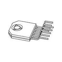
Philips Semiconductors 15. Package outline DBS9P: plastic DIL-bent-SIL power package; 9 leads (lead length 12/11 mm); exposed die pad DIMENSIONS (mm are the original dimensions) (2) (1) (2) UNIT ...
Page 16
Philips Semiconductors 16. Soldering 16.1 Introduction to soldering through-hole mount packages This text gives a brief insight to wave, dip and manual soldering. A more in-depth account of soldering ICs can be found in our Data Handbook IC26; Integrated Circuit ...
Page 17
Philips Semiconductors 17. Revision history Table 11. Revision history Document ID Release date TFA9843AJ_1 20060428 TFA9843AJ_1 Preliminary data sheet 20 W stereo power amplifier with volume control Data sheet status Change notice Preliminary data sheet - Rev. 01 — 28 ...
Page 18
Philips Semiconductors 18. Legal information 18.1 Data sheet status [1][2] Document status Product status Objective [short] data sheet Development Preliminary [short] data sheet Qualification Product [short] data sheet Production [1] Please consult the most recently issued document before initiating or ...
Page 19
Philips Semiconductors 20. Contents 1 General description . . . . . . . . . . . . . . . . . . . . . . 1 2 Features . . . . . . . . ...