TFA9812HN/N1,518 NXP Semiconductors, TFA9812HN/N1,518 Datasheet
TFA9812HN/N1,518
Specifications of TFA9812HN/N1,518
TFA9812HN/N1-T
TFA9812HN/N1-T


Related parts for TFA9812HN/N1,518


TFA9812HN/N1,518 Summary of contents
Page 1
TFA9812 BTL stereo Class-D audio amplifier with I Rev. 02 — 22 January 2009 1. General description The TFA9812 is a high-efficiency Bridge Tied Load (BTL) stereo Class-D audio amplifier with a digital I paddle. The exposed die paddle technology ...
Page 2
... NXP Semiconductors I No high system clock required (PLL is able to lock on BCK external heat sink required tolerant digital inputs I Supports dual coil inductor application I Easy application and limited external components required 2.2 DSP features I Digital parametric 10-band equalizer I Digital volume control per channel ...
Page 3
... NXP Semiconductors 4. Quick reference data Table 1. Unless specified otherwise SS1 2 24-bit I S input data, MCLK clock mode, typical application diagram Symbol General V DDA V DDP V DDA(3V3) V DDD(3V3 DDA(3V3) I DDD(3V3) P o(RMS the current through the analog supply voltage (V P voltage (V TFA9812_2 Preliminary data sheet BTL stereo Class-D audio amplifi ...
Page 4
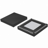
... NXP Semiconductors 5. Ordering information Table 2. Ordering information Type number Package Name TFA9812HN HVQFN48 TFA9812_2 Preliminary data sheet BTL stereo Class-D audio amplifier with I Description plastic thermal enhanced very thin quad flat package; no leads; 48 terminals; body 7 7 0.85 mm Rev. 02 — 22 January 2009 ...
Page 5
Block diagram TEST1 TEST2 7 43 PHASED REGISTER LOCKED ADDRESS LOOP HEX 01 XTALIN 1 CLOCK OSCILLATOR PROTECTION XTALOUT 2 LP UFP MCLK 47 OFP IBP BCK 46 VOLUME SERIAL 10-BAND WS 45 CONTROL AUDIO PARAMETRIC AND SOFT DATA ...
Page 6
... NXP Semiconductors Figure 1 signal path see 7. Pinning information 7.1 Pinning Fig 2. Table 3. Pin TFA9812_2 Preliminary data sheet BTL stereo Class-D audio amplifier with I shows the block diagram of the TFA9812. For a detailed description of the audio Section 8.1. terminal 1 index area XTALIN ...
Page 7
... NXP Semiconductors Table 3. Pin TFA9812_2 Preliminary data sheet BTL stereo Class-D audio amplifier with I Pinning description TFA9812 …continued Symbol Type Description OUT2N O Negative PWM output channel 2 BOOT1P O Bootstrap high-side driver positive PWM output channel 1 OUT1P O Positive PWM output channel 1 OUT1P ...
Page 8
... NXP Semiconductors Table 3. Pin 47 48 Exposed die-paddle 8. Functional description 8.1 General The TFA9812 is a high-efficiency stereo BTL Class-D amplifier with a digital I input. It supports all commonly used I Figure 1 TFA9812. In the digital domain the audio signal is processed and converted to a pulse width modulated signal using BD modulation. A BTL confi ...
Page 9
... NXP Semiconductors The block control defines the operational control settings of the TFA9812 in line with the actual I The PLL block creates the system clock and can take the I external crystal as reference source. The following protections are built into the TFA9812: • Thermal Foldback (TF) • ...
Page 10
... NXP Semiconductors • In Soft mute mode the I – In Legacy control mode the analog input pin AVOL controls Soft mute mode. – function. See also • In Hard mute mode the PWM controller is overruled with duty cycle square pulse. The Hard mute mode is only available in I • ...
Page 11
... NXP Semiconductors Table 6. Pin value CSEL [1] Under these conditions the mode is enabled by the appropriate slave mode selection between BCK and MCLK clock modes is automatic. MCLK clock mode is given higher priority than BCK. If the MCLK clock is judged valid by the protection circuit then MCLK clock mode is enabled. BCK clock mode is enabled when the MCLK clock is invalid (e ...
Page 12
... NXP Semiconductors Table 8. Control mode Legacy Table 9. Control mode Legacy [1] The valid sample frequencies are shown in TFA9812_2 Preliminary data sheet BTL stereo Class-D audio amplifier with I 2 Valid MCLK frequencies slave mode f (kHz 44 Valid BCK frequencies slave mode f (kHz) s [1] ...
Page 13
... NXP Semiconductors 8.3 Power-up/power-down external voltage supplies POWERUP ENABLE available soft mute setting mode AVOL pin in Legacy mode PWM outputs Operating mode active Fig 3. 8.3.1 Power-up Figure 3 for initiating a power-up reset. Table 10. Symbol t wake t d(on) t d(mute_off) t d(soft_mute) [1] Mute in Legacy mode is controlled by AVOL pin. ...
Page 14
... NXP Semiconductors control mode communication is enabled after 4 ms. The preferred I be made within 66 ms before the PLL starts running. Finally, the output stages are enabled and the audio level is increased via a demute sequence if mute has previously been disabled. Remark communication is valid. In order to prevent audio clicks volume control (default setting is 0 dB) should be set before soft mute is disabled ...
Page 15
... NXP Semiconductors Table 12. BCK frequency Interface format (MSB first Remark: Only MSB-first formats are supported. WS LEFT BCK DATA MSB B2 WS LEFT BCK DATA MSB B2 MSB-JUSTIFIED FORMAT WS LEFT BCK DATA WS LEFT BCK DATA WS LEFT 20 BCK DATA MSB WS LEFT BCK DATA MSB B2 ...
Page 16
... NXP Semiconductors control mode the following sample frequency f 12 kHz, 16 kHz, 22.05 kHz, 24 kHz, 32 kHz, 44.1 kHz, 48 kHz, 64 kHz, 88.2 kHz, 96 kHz, 128 kHz, 176.4 kHz or 192 kHz. The I Section In Legacy control mode the following sample frequencies (f 44.1 kHz or 48 kHz. ...
Page 17
... NXP Semiconductors In the above equation f The definition of the quality factor is the center frequency divided by the 3 dB bandwidth, see Equation ( 30 dB -----------------; f 2 Each band filter can be programmed to perform a band-suppression (G < band-amplification (G > 1) function around the center frequency. Each band of the TFA9812 equalizer has a second-order Regalia-Mitra all-pass filter structure ...
Page 18
... NXP Semiconductors The ranges of the TFA9812 parametric equalizer settings for each band are: • The Gain from +12 dB. • The center frequency, f • The quality factor Q is from 0.001 Using I as desired. Figure 6, equalizer bands. The relations are symmetrical for the suppression and amplification functions. A skewing effect can be observed for the higher frequencies. Different confi ...
Page 19
... NXP Semiconductors Equation example, in word2 bits [14:8] = [0111 010] represent k Table 15. Word word1 word1 word1 word2 word2 word2 word2 word2 Section 9.5.4 equalizer. Fig 6. TFA9812_2 Preliminary data sheet BTL stereo Class-D audio amplifier with I – – – the unsigned mantissa and E the negative signed exponent. For ...
Page 20
... NXP Semiconductors Gain (dB) Fig 7. Gain (dB) Fig 8. 8.5.2 Digital volume control control mode both audio channels have separate digital volume control. In Legacy control mode the volume control of both channels is common and the volume control setting depends on the supply voltage on the pin AVOL (32). ...
Page 21
... NXP Semiconductors Table 16. [7:0] control value (hexadecimal ... Section 9 In Legacy mode the pin AVOL (32) can be used to control the volume. Voltage levels of 0 2.8 V correspond linearly to control values of 00h (0 dB) to F9h (mute). See An external pull-up resistor connected to the V volume of 0 dB. Pin AVOL has no function ...
Page 22
... NXP Semiconductors Table 17. GAIN pin value The I C controls for selecting the +24 dB gain can be found in pin has no function In I The TFA9812 features also specific gain settings which are related to < 0 clipping at the output of the TFA9812. These clipping values are only valid under the following conditions: • ...
Page 23
... NXP Semiconductors The selected PWM switching frequency is 400 kHz by default and can be set to 350 kHz, 700 kHz and 750 kHz in I this scales linearly if 32 kHz or 48 kHz is used as f Remark: The selected sample frequency, f frequency (f Remark: The performance of AM radio reception can sometimes be improved by selecting non-interfering frequencies for the PWM signal. 8.6 Class-D amplifi ...
Page 24
... NXP Semiconductors 8.7.1 Thermal foldback If the junction temperature of the TFA9812 exceeds the programmable Thermal foldback threshold temperature the gain of the amplifier is decreased gradually to a level where the combination of dissipation (P) and the thermal resistance from junction to ambient (R results in a junction temperature around the threshold temperature. ...
Page 25
... NXP Semiconductors Table 20. Pin name V DDA V DDA(3V3) 8.7.6 Overdissipation protection When the output current of the power amplifiers exceeds a current value and the temperature is above 140 C, overdissipation protection is activated and the device enters Sleep mode. A restart will be initiated automatically when the two overdissipation conditions are both changed to ‘ ...
Page 26
... NXP Semiconductors 8.7.11 Invalid BCK protection The BCK clock signal is verified as being at one of the allowed relative frequencies 3-state mode to prevent audible effects. The MCLK clock signal is also verified as being valid, see Detection of violation results in an automatic internal overruling of the MCLK assignment to BCK ...
Page 27
... NXP Semiconductors Table 21. Protections Symbol Conditions OFP IBP [1] See, [2] Window Protection is only checked at power-up bus interface and register settings 2 9 bus interface The TFA9812 supports the 400 kHz I can be used to control the TFA9812 and to exchange data with it when in I mode, see ...
Page 28
... NXP Semiconductors 2 9 write cycle description Table 25 byte size is 8 bits. The I written in pairs of two bytes. Data transfer is always MSB first. The cycle format for writing to the TFA9812 using SDA is as follows: 1. The microcontroller asserts a start condition (S). 2. The microcontroller sends the device address (7 bits) of the TFA9812 followed by the R/!W bit set to 0 ...
Page 29
... NXP Semiconductors 9. The TFA9812 sends the first byte. This is the most significant byte of the register. 10. The microcontroller asserts an acknowledge. 11. The TFA9812 sends the second byte. 12. The microcontroller asserts either an acknowledge or a negative acknowledge (NA). – If the microcontroller has asserted an acknowledge, the targeted register address is auto-increased by the TFA9812 and steps are repeated. – ...
Page 30
... NXP Semiconductors Table 27. Register address (hex) 0x11 0x12 0x13 0x14 0x15 0x16 0x17 0x18 0x19 0x1A 0x1B 0x1C 0x1D 0x1E 0x1F 0x20 0x21 0x22 0x23 0x24 0x25 0x26 0x27 0x28 0x29 0x2A 0x2B 0x2C 0x2D 0x2E 0x2F 0x30 Reserved registers or bits will be indicated by RSD. ...
Page 31
... NXP Semiconductors 9.5.1 Interpolator settings and soft mute Table 28. Register address 00h: miscellaneous I Bit 15 Symbol RSD RSD Default 0 Bit 7 Symbol RSD INV_POL Default 0 Table 29. Bit 9.5.2 Volume control Table 30. Register address 01h: volume control Bit 15 Symbol VOL_L7 VOL_L6 Default 0 Bit 7 Symbol ...
Page 32
... NXP Semiconductors Table 31. Bit 9.5.3 Digital input format Table 32. Register address 02h: digital input format Bit 15 Symbol RSD RSD Default 0 Bit 7 Symbol RSD RSD Default 0 Table 33. Bit 9.5.4 Equalizer configuration Table 34. Register address 03h: equalizer configuration Bit 15 Symbol RSD ...
Page 33
... NXP Semiconductors Table 35. Bit 1 0 9.5.5 Equalizer settings Table 36. Register addresses xxh = 04, 06...2A For word1 for equalizer 'yy' see Figure 9 Bit 15 Symbol Eyy_t Eyy_k 1 [1] Default - Bit 7 Symbol Eyy_k 3 Eyy_k 1m [1] Default - [1] Default settings are shown in Table Table 37. Register addresses xxh = 05, 07...2B ...
Page 34
... NXP Semiconductors Left in Right in Fig 9. Equalizer configuration and register location mapping Table 38. Bit Table 39. Bit TFA9812_2 Preliminary data sheet BTL stereo Class-D audio amplifier with Bit description of registers xxh = 04, 06...2A Symbol Description Eyy_t The filter configuration bit t 1 Eyy_k1 [10:0] The 11 mantissa bits of the fi ...
Page 35
... NXP Semiconductors Table 40. Default configuration equalizer for f Band A1/B1 A2/B2 Frequency 31 63 (Hz) Q-factor 1 1 Gain (dB 9.5.6 PWM signal control Table 41. Register 2Ch: PWM signal control Bit 15 14 Symbol RSD RSD Default 0 0 Bit 7 6 Symbol RSD PLIM1 Default 0 0 Table 42. ...
Page 36
... NXP Semiconductors 9.5.7 Digital-in clock configuration Table 43. Register 2Dh: digital-in clock configuration Bit 15 Symbol RSD RSD Default 0 Bit 7 Symbol RSD RSD Default 0 Table 44. Bit 9.5.8 Thermal foldback control Table 45. Register 2Eh: thermal foldback control Bit 15 Symbol RSD RSD Default ...
Page 37
... NXP Semiconductors Table 46. Bit 9.5.9 TFA9812 temperature Table 47. Register 2Fh: TFA9812 temperature Bit 15 Symbol RSD RSD Default - Bit 7 Symbol TEMP7 TEMP6 Default - Table 48. Bit 9.5.10 Miscellaneous status Table 49. Register 30h: miscellaneous status Bit 15 Symbol RSD RSD Default - Bit 7 Symbol RSD OFP ...
Page 38
... NXP Semiconductors Table 50. Bit [1] The diagnostic pin 30 DIAG is flagged when several protection mechanisms have been active, see Section 9.6 Overview of functional control in each control mode Table 51 functions described in description of each function. Table 51 fixed control setting, determined by default I supported (i.e. all options implemented in the TFA9812). ...
Page 39
... NXP Semiconductors Table 51 fixed control setting, determined by default I supported (i.e. all options implemented in the TFA9812). Control function Clip level control Output power limit level control PWM signal frequency selection Thermal foldback threshold temperature control [1] 32 kHz, 44.1 kHz and 48 kHz supported [2] Bypass ...
Page 40
... NXP Semiconductors Table 52. Pin 10/11 18/19 26/ TFA9812_2 Preliminary data sheet BTL stereo Class-D audio amplifier with I Internal circuitry …continued Symbol Equivalent circuitry STABA STABD REFA V DDA TEST1 STAB2 STAB1 V SSP2 V DDP V SSP1 BOOT2N BOOT1P BOOT2P BOOT1N Rev. 02 — 22 January 2009 ...
Page 41
... NXP Semiconductors Table 52. Pin 13/14 16/17 20/21 23/ TFA9812_2 Preliminary data sheet BTL stereo Class-D audio amplifier with I Internal circuitry …continued Symbol Equivalent circuitry OUT2N OUT1P OUT2P OUT1N DIAG CDELAY POWERUP ENABLE GAIN CSEL ADSEL2/PLIM2 ADSEL1/PLIM1 TEST2 Rev. 02 — 22 January 2009 ...
Page 42
... NXP Semiconductors Table 52. Pin 11. Limiting values Table 53. Limiting values In accordance with the Absolute Maximum Rating System (IEC 60134). Symbol Parameter V analog supply voltage DDA V power supply voltage DDP V analog supply voltage (3.3 V) DDA(3V3) V digital supply voltage (3.3 V) DDD(3V3) T junction temperature j T storage temperature ...
Page 43
... NXP Semiconductors Table 53. Limiting values …continued In accordance with the Absolute Maximum Rating System (IEC 60134). Symbol Parameter V voltage on pin electrostatic discharge voltage esd [ REFA = REFD ss SS1 SS2 12. Thermal characteristics Table 54. Symbol R th(j-a) R th(j-c) R th(j-lead) [1] Measured in a JEDEC high K-factor test board (standard EIA/JESD 51-7). ...
Page 44
... NXP Semiconductors 13. Characteristics 13.1 DC Characteristics Table 55. DC characteristics Unless specified otherwise, V DDA REFD = REFA = SS1 SS2 MCLK clock mode, typical application diagram Symbol Parameter Supply voltage V analog supply DDA voltage V power supply voltage DDP V analog supply DDA(3V3) voltage (3 digital supply voltage DDD(3V3) (3 ...
Page 45
... NXP Semiconductors Table 55. DC characteristics …continued Unless specified otherwise, V DDA REFD = REFA = SS1 SS2 MCLK clock mode, typical application diagram Symbol Parameter V HIGH-level output OH voltage V LOW-level output OL voltage C load capacitance L SDA/MS, SCL/SFOR pin V HIGH-level input IH voltage V LOW-level input IL voltage V input hysteresis ...
Page 46
... NXP Semiconductors Table 55. DC characteristics …continued Unless specified otherwise, V DDA REFD = REFA = SS1 SS2 MCLK clock mode, typical application diagram Symbol Parameter Thermal Foldback (TF) T thermal foldback act(th_fold) activation temperature OverTemperature Protection (OTP) T thermal protection act(th_prot) activation temperature OverVoltage Protection (OVP) ...
Page 47
... NXP Semiconductors 13.2 AC characteristics Table 56. AC characteristics Unless specified otherwise, V DDA kHz 44.1 kHz 400 kHz, 24-bit Symbol Parameter Output power per channel P RMS output power o(RMS) Performance THD+N total harmonic distortion-plus-noise S/N signal-to-noise ratio V output noise voltage n(o) channel separation ...
Page 48
... NXP Semiconductors Table 56. AC characteristics …continued Unless specified otherwise, V DDA kHz 44.1 kHz 400 kHz, 24-bit Symbol Parameter t propagation delay PD PWM output t rise time r t fall time f t minimum pulse width w(min) R drain-source on-state resistance DSon maximum duty factor max ...
Page 49
... NXP Semiconductors 2 Table 57. Characteristics I C bus interface; see 2 3 DDD(3V3) DDA(3V3) unless otherwise specified. Symbol Parameter t set-up time for STOP condition SU;STO t bus free time between a STOP and BUF START condition t data set-up time SU;DAT t data hold time HD;DAT t pulse width of spikes that must be SP suppressed by the input fi ...
Page 50
... NXP Semiconductors = Maximum duty factor (0.96). max The output power THD can be estimated using P (10%) O Figure 11 THD = function of BTL supply voltage for different load impedances (0 (W/channel (1) 6 (2) 8 (3) 16 Fig 11. BTL P (0 function 14.2 Output current limiting The peak output current is internally limited above a level minimum. During normal operation the output current should not exceed this threshold level otherwise the output signal will be distorted ...
Page 51
... NXP Semiconductors Remark: A 4.8 used supply voltage without running into current limiting. Current limiting (clipping) will avoid audio holes, but it causes a distortion comparable to voltage clipping. 14.3 Speaker configuration and impedance For a flat-frequency response (second-order Butterworth filter necessary to change the low pass filter components L impedance ...
Page 52
I S slave mode and Legacy control mode DIAGNOSTIC POWERUP DC-VOLUME CONTROL ENABLE ADSEL1/PLIM1 38 SCL/SFOR 39 SDA/ DDD(3V3) DDD 41 STABD C vddd C STABD 1 F 100 nF 42 REFD ...
Page 53
I S slave mode and I DIAGNOSTIC POWERUP ENABLE 3 ADSEL1/PLIM1 SCL 38 SCL/SFOR SDA SDA/MS 40 VDDD V DDD(3V3) 41 STABD C VDDD C STABD 100 ...
Page 54
I S master mode and Legacy control mode DIAGNOSTIC POWERUP DC-VOLUME CONTROL ENABLE ADSEL1/PLIM1 38 SCL/SFOR 39 3.3 V SDA/ DDD(3V3) DDD 41 STABD C vddd C STABD 1 F 100 nF ...
Page 55
I S master mode and I DIAGNOSTIC POWERUP ENABLE 3 ADSEL1/PLIM1 SCL 38 SCL/SFOR SDA SDA/MS 40 VDDD V DDD(3V3) 41 STABD C VDDD C STABD 100 ...
Page 56
... NXP Semiconductors 14.5 Curves measured in typical application 10 THD+N (%) 1 ( kHz i ( kHz i ( 100 THD+N (%) kHz i ( kHz i ( 100 Fig 17. Total harmonic distortion-plus-noise as a function of output power TFA9812_2 Preliminary data sheet BTL stereo Class-D audio amplifier with I 010aaa480 10 THD+N (%) (W/channel) o (1) f ( ...
Page 57
... NXP Semiconductors 10 THD+N (%) Fig 18. Total harmonic distortion-plus-noise as a function of frequency 3 G (dB ( 680 680 F L Fig 19. Gain as a function of frequency TFA9812_2 Preliminary data sheet BTL stereo Class-D audio amplifier with I 010aaa484 10 THD+N (%) (Hz 010aaa486 G (dB (1) 60 (2) 80 100 120 (Hz gain boost Fig 20. Gain as a function of AVOL Rev. 02 — ...
Page 58
... NXP Semiconductors 0 SVRR (dB 100 500 mV (RMS) reference to ground; P ripple No input signal ( ( Fig 21. SVRR as a function of frequency (W/chan.) 20 (1) 15 ( 120 240 360 ( 125 C act(th_fold) ( 105 C act(th_fold) ( act(th_fold) Fig 23. Output power as a function of time TFA9812_2 Preliminary data sheet BTL stereo Class-D audio amplifier with I ...
Page 59
... NXP Semiconductors (W/chan (1) Power limiter = 0 dB (2) Power limiter = 1.5 dB (3) Power limiter = 3 dB (4) Power limiter = 4 (W/chan (1) Power limiter = 0 dB (2) Power limiter = 1.5 dB (3) Power limiter = 3 dB (4) Power limiter = 4 Fig 24. Output power as a function of supply voltage TFA9812_2 Preliminary data sheet BTL stereo Class-D audio amplifier with I ...
Page 60
... NXP Semiconductors 3 P ( kHz; Power dissipation in junction only Fig 25. Power dissipation as a function of output power ( ( Fig 27. Channel separation as a function of frequency TFA9812_2 Preliminary data sheet BTL stereo Class-D audio amplifier with I 010aaa496 100 PO (%) (W/channel) o (1) R (2) R Fig 26. Efficiency as a function of output power ...
Page 61
... NXP Semiconductors 15. Package outline HVQFN48: plastic thermal enhanced very thin quad flat package; no leads; 48 terminals; body 0.85 mm terminal 1 index area terminal 1 48 index area DIMENSIONS (mm are the original dimensions) (1) A UNIT max 0.05 0. 0.2 0.00 0.18 Note 1. Plastic or metal protrusions of 0.075 mm maximum per side are not included. ...
Page 62
... NXP Semiconductors 16. Handling information It is advisable to abide by the normal precautions appropriate to handling MOS devices. TFA9812_2 Preliminary data sheet BTL stereo Class-D audio amplifier with I Rev. 02 — 22 January 2009 TFA9812 2 S input © NXP B.V. 2009. All rights reserved ...
Page 63
... NXP Semiconductors 17. Revision history Table 59. Revision history Document ID Release date TFA9812_2 20090122 • Modifications: Table 55 “DC characteristics” TFA9812_1 2008/10/30 TFA9812_2 Preliminary data sheet BTL stereo Class-D audio amplifier with I Data sheet status Change notice Preliminary data sheet - V maximum value updated. ...
Page 64
... Right to make changes — NXP Semiconductors reserves the right to make changes to information published in this document, including without limitation specifications and product descriptions, at any time and without notice ...
Page 65
... NXP Semiconductors 20. Contents 1 General description . . . . . . . . . . . . . . . . . . . . . . 1 2 Features . . . . . . . . . . . . . . . . . . . . . . . . . . . . . . . 1 2.1 General features . . . . . . . . . . . . . . . . . . . . . . . . 1 2.2 DSP features . . . . . . . . . . . . . . . . . . . . . . . . . . 2 2.3 Audio data input interface format support Applications . . . . . . . . . . . . . . . . . . . . . . . . . . . . 2 4 Quick reference data . . . . . . . . . . . . . . . . . . . . . 3 5 Ordering information . . . . . . . . . . . . . . . . . . . . . 4 6 Block diagram . . . . . . . . . . . . . . . . . . . . . . . . . . 5 7 Pinning information . . . . . . . . . . . . . . . . . . . . . . 6 7.1 Pinning . . . . . . . . . . . . . . . . . . . . . . . . . . . . . . . 6 8 Functional description . . . . . . . . . . . . . . . . . . . 8 8.1 General . . . . . . . . . . . . . . . . . . . . . . . . . . . . . . . 8 8 ...
Page 66
... NXP Semiconductors 18.4 Trademarks . . . . . . . . . . . . . . . . . . . . . . . . . . . 64 19 Contact information Contents . . . . . . . . . . . . . . . . . . . . . . . . . . . . . . 65 BTL stereo Class-D audio amplifier with I Please be aware that important notices concerning this document and the product(s) described herein, have been included in section ‘Legal information’. © NXP B.V. 2009. For more information, please visit: http://www.nxp.com For sales office addresses, please send an email to: salesaddresses@nxp ...