TDA7563 STMicroelectronics, TDA7563 Datasheet
TDA7563
Specifications of TDA7563
Available stocks


Related parts for TDA7563


TDA7563 Summary of contents
Page 1
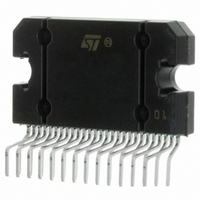
... Bridge type of car radio amplifier in Flexiwatt27 package specially intended for car radio applica- tions. Thanks to the DMOS output stage the TDA7563 has a very low distortion allowing a clear powerful sound. Among the features, its superior efficiency performance coming from the internal ex- ...
Page 2
... TDA7563 ABSOLUTE MAXIMUM RATINGS Symbol V Operating Supply Voltage Supply Voltage S V Peak Supply Voltage (for t = 50ms) peak V CK pin Voltage CK V Data Pin Voltage DATA I Output Peak Current (not repetitive t = 100ms Output Peak Current (repetitive f > 10Hz Power Dissipation T tot case ...
Page 3
... Figure 1. Application Circuit V( DATA BUS CLK 0.1 F 3300 F Vcc1 Vcc2 S-GND OUT + 18 19 OUT OUT OUT OUT TAB 1, 27 47K V D00AU1231A TDA7563 3/20 ...
Page 4
... TDA7563 ELECTRICAL CHARACTERISTICS (Refer to the test circuit 14.4V Symbol Parameter POWER AMPLIFIER V Supply Voltage Range S I Total Quiescent Drain Current d P Output Power O THD Total Harmonic Distortion C Cross Talk T R Input Impedance IN G Voltage Gain Voltage Gain Match Voltage Gain 2 V2 ...
Page 5
... Test Condition D0 (IB1 Power Amplifier in st-by Power Amplifier in st-by Power Amplifier in Mute or Play, one or more short circuits protection activated Pow. Amp. mode Line Driver mode Power Amplifier in play, AC Input signals = 0 TDA7563 = 25°C; unless otherwise specified.) Min. Typ. Max. Unit 1 ...
Page 6
... TDA7563 Figure 2. Quiescent Current vs. Supply Voltage Id (mA) 250 230 Vin = 0 210 NO LOADS 190 170 150 130 110 (V) Figure 3. Output Power vs. Supply Voltage ( ( Ohm KHz (V) Figure 4. Output Power vs. Supply Voltage ( (W) 100 Ohm KHz (V) 6/20 Figure 5. Distortion vs. Output Power (4 , STD) THD (%) 10 1 0.1 ...
Page 7
... Figure 12. Power Dissipation & Efficiency vs. Output Power (4 , STD, SINE) Ptot (W) 90 STANDARD MODE 14 Ohm KHz SINE 10000 Figure 13. Power Dissipation & Efficiency vs. Output Power (4W, HI-EFF, SINE) Ptot ( 10000 0.1 TDA7563 1000 10000 f (Hz) n (%) Ptot (W) n (%) 90 HI-EFF MODE 14 Ohm KHz SINE 60 50 Ptot (W) 7/20 ...
Page 8
... TDA7563 Figure 14. Power Dissipation vs. Average Ouput Power (Audio Program Simulation Ptot ( Ohm 35 GAUSSIAN NOISE 30 CLIP 25 START (W) DIAGNOSTICS FUNCTIONAL DESCRIPTION: a) TURN-ON DIAGNOSTIC It is activated at the turn-on (stand-by out) under I – SHORT TO GND – SHORT TO Vs – SHORT ACROSS THE SPEAKER – OPEN SPEAKER To verify if any of the above misconnections are in place, a subsonic (inaudible) current pulse (fig ...
Page 9
... Typ) Diagnostic Enable FAULT (Permanent) event Permanent Diagnostics data (output) permitted time Turn-on Diagnostics data (output) Diagnostic Enable permitted time Read Data TDA7563 Read Data Permanent diagnostic acquisition time (100mS Typ) FAULT event (Permanent) Permanent Diagnostics data (output) permitted time t t ...
Page 10
... The following additional features are provided: – OUTPUT OFFSET DETECTION The TDA7563 has 2 operating statuses: 1 RESTART mode. The diagnostic is not enabled. Each audio channel operates independently from each other. If any of the a.m. faults occurs, only the channel(s) interested is shut down. A check of the output status is made every 1 ms (fig ...
Page 11
... The test is run with selectable time duration by microprocessor (from a "start" "stop" command): – START = Last reading operation or setting IB1 - D5 - (OFFSET enable reading. This is to ensure continuous diagnostics 1mS 1mS 1mS 1mS Short circuit removed 100/200mS TDA7563 Out t 1mS 1mS t Short circuit removed 11/20 ...
Page 12
... TDA7563 – STOP = Actual reading operation Excess offset is signalled out if persistent throughout the assigned testing time. This feature is disabled if any overloads leading to activation of the short-circuit protection occurs in the process. MULTIPLE FAULTS When more misconnections are simultaneously in place at the audio outputs guaranteed that at least one of them is initially read out ...
Page 13
... Car Radio Installation: PIN2 > 7V --- 10ms DIAG ENABLE (write) --- 200 ms --- I disappear). OFFSET TEST: Device in Play (no signal) -- OFFSET ENABLE - 30ms - I high-offset message disappears). TH. WARN. ON TH. SH. TH. SH. START END < T > T (with same input SD SD signal) TDA7563 Tj ( ° ° ° read (repeat until All faults reading (repeat I C reading until 13/20 ...
Page 14
... I C BUS INTERFACE Data transmission from microprocessor to the TDA7563 and viceversa takes place through the 2 wires I face, consisting of the two lines SDA and SCL (pull-up resistors to positive supply voltage must be connected). Data Validity As shown by fig. 22, the data on the SDA line must be stable during the high period of the clock. The HIGH and LOW state of the data line can only change when the clock signal on the SCL line is LOW ...
Page 15
... SOFTWARE SPECIFICATIONS All the functions of the TDA7563 are activated by I The bit 0 of the "ADDRESS BYTE" defines if the next bytes are write instruction (from P to TDA7563) or read instruction (from TDA7563 to P). Chip Address Write to device Read from device If R the P sends 2 "Instruction Bytes": IB1 and IB2. ...
Page 16
... TDA7563 If R the TDA7563 sends 4 "Diagnostics Bytes" DB1, DB2, DB3 and DB4. DB1 D7 Thermal warning active ( Diag. cycle not activated or not terminated ( Diag. cycle terminated ( Channel LF Turn-on diagnostic ( Permanent diagnostic ( Channel LF Normal load ( Short load ( Channel LF Turn-on diag.: No open load ( Open load detection ( Offset diag ...
Page 17
... Short to GND ( DB4 Channel RR Turn-on diagnostic ( Permanent diagnostic ( Channel R RNormal load ( Short load ( Channel RR Turn-on diag.: No open load ( Open load detection ( Permanent diag.: No output offset ( Output offset detection ( Channel RR No short to Vcc ( Short to Vcc ( Channel RR No short to GND ( Short to GND ( TDA7563 17/20 ...
Page 18
... TDA7563 Examples of bytes sequence 1 - Turn-On diagnostic - Write operation Start Address byte with Turn-On diagnostic - Read operation Start Address byte with The delay from can be selected by software, starting from T.B. Turn-On of the power amplifier with 30dB gain, mute on, diagnostic defeat 2%. Start Address byte with ...
Page 19
... Flexiwatt27 (vertical TDA7563 OUTLINE AND FLEX27ME M M1 7139011 19/20 ...
Page 20
... TDA7563 Information furnished is believed to be accurate and reliable. However, STMicroelectronics assumes no responsibility for the consequences of use of such information nor for any infringement of patents or other rights of third parties which may result from its use. No license is granted by implication or otherwise under any patent or patent rights of STMicroelectronics. Specifications mentioned in this publication are subject to change without notice ...