TDA7490 STMicroelectronics, TDA7490 Datasheet
TDA7490
Specifications of TDA7490
Available stocks


Related parts for TDA7490


TDA7490 Summary of contents
Page 1
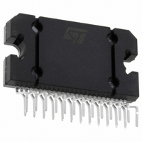
... December 2005 25W + 25W STEREO CLASS-D AMPLIFIER Figure 1. Package Table 1. Order Codes Part Number 2 DESCRIPTION The TDA7490 is a dual audio class D amplifier as- sembled in Flexiwatt 25 package specially de- signed for high efficiency application mainly for TV and Home Stereo sets. R17 52. C26 470pF C25 470pF R21 4 ...
Page 2
... TDA7490 Figure 3. Test and Application Circuit. (Bridge Configuration) INPUT 10 PRE R63 4.7K PRE 18 Table 2. Absolute Maximum Ratings Symbol V DC Supply Voltage (no signal Power Dissipation T tot case Storage and Junction Temperature stg j T Operating Temperature Range op V Maximum Voltage on pins # 6,8,10,18 referred to GND 6,8,10,18 Table 3 ...
Page 3
... FEED3 Feedback pin1 CH2 18 IN2 Input CH2 19 FEED4 Feedback pin2 CH2 20 NC Not connected 21 BOOT2 Bootstrap CH2 22 +V Positive power supply CH2 CCpow2 23 OUT2 PWM output of CH2 24 -V Negative power supply CH2 CCpow2 25 V 10V regulator reg 25 D97AU816B Function TDA7490 3/10 ...
Page 4
... TDA7490 Table 5. Electrical Characteristics (Refer to the test circuit ±21V 25°C unless otherwise specified.) amb Symbol Parameter V Supply Range S I Total Quiescent Current q V Output Offset Voltage OS P Output Power o P Output Power in Bridge o(BTL) Configuration (1) Output Power Maximum Dissipated Power D Efficiency (*) η ...
Page 5
... Figure 5. P.C. Board and Component Layout of the Figs (for Stereo and Bridge Compatible Configuration) TDA7490 Component Side Solder Side 5/10 ...
Page 6
... TDA7490 Figure 6. Distortion vs. Output Power THD (%) 5 Stereo V ± 21V; Rl=8Ω; S f=1KHz 2 1 0.5 0.2 0.1 0.05 0.02 0. Figure 7. Distortion vs. Output Power THD (%) 5 Stereo V ± 16V; Rl=4Ω; S f=1KHz 2 1 0.5 0.2 0.1 0.05 0.02 0. Figure 8. Crosstalk vs. Frequency CT (dB) V ± 17V; ...
Page 7
... Figure 12. Distortion vs. Output Power in BTL THD (%) Bridge 5 V ± 22V; S Rl=16Ω; 2 f=1KHz 1 0.5 0.2 0.1 0.05 0.02 0. D99AU1083 (W) O TDA7490 7/10 ...
Page 8
... TDA7490 Figure 13. Package Dimensions mm DIM. MIN. TYP. MAX. A 4.45 4.50 4.65 B 1.80 1.90 2.00 C 1.40 D 0.75 0.90 1.05 E 0.37 0.39 0.42 F (1) 0.57 G 0.80 1.00 1.20 G1 23.75 24.00 24.25 H (2) 28.90 29.23 29.30 H1 17.00 H2 12.80 H3 0.80 L (2) 22.07 22.47 22.87 L1 18.57 18 ...
Page 9
... Table 6. Revision History Date Revision March 2001 5 December 2005 6 Description of Changes First Issue Corrected the value of the inductance in the caption of the Table 5 “Electrical Characteristics”. TDA7490 9/10 ...
Page 10
... TDA7490 Information furnished is believed to be accurate and reliable. However, STMicroelectronics assumes no responsibility for the consequences of use of such information nor for any infringement of patents or other rights of third parties which may result from its use. No license is granted by implication or otherwise under any patent or patent rights of STMicroelectronics. Specifications mentioned in this publication are subject to change without notice ...