TDA7575 STMicroelectronics, TDA7575 Datasheet - Page 15
TDA7575
Manufacturer Part Number
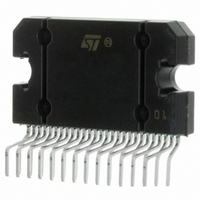
TDA7575
Description
IC AMP AUDIO 150W AB 27FLEXIWATT
Manufacturer
STMicroelectronics
Type
Class ABr
Specifications of TDA7575
Output Type
1-Channel (Mono) or 2-Channel (Stereo)
Max Output Power X Channels @ Load
150W x 1 @ 1 Ohm; 75W x 2 @ 2 Ohm
Voltage - Supply
8 V ~ 18 V
Features
Differential Inputs, I²C, Mute, Short-Circuit and Thermal Protection, Standby
Mounting Type
Through Hole
Package / Case
27-Flexiwatt (bent and staggered leads)
Operational Class
Class-AB
Output Power (typ)
150x1@1Ohm/75x2@2OhmW
Audio Amplifier Function
Speaker
Total Harmonic Distortion
0.02@1Ohm@30W%
Single Supply Voltage (typ)
9/12/15V
Dual Supply Voltage (typ)
Not RequiredV
Power Supply Requirement
Single
Power Dissipation
86W
Rail/rail I/o Type
No
Single Supply Voltage (min)
8V
Single Supply Voltage (max)
18V
Dual Supply Voltage (min)
Not RequiredV
Dual Supply Voltage (max)
Not RequiredV
Operating Temp Range
-55C to 150C
Operating Temperature Classification
Military
Mounting
Surface Mount
Pin Count
36
Package Type
PSOP
Lead Free Status / RoHS Status
Lead free / RoHS Compliant
Available stocks
Company
Part Number
Manufacturer
Quantity
Price

Company:
Part Number:
TDA7575B BC
Manufacturer:
SMD
Quantity:
2
Part Number:
TDA7575B-BC
Manufacturer:
ST
Quantity:
20 000
Part Number:
TDA7575BBC
Manufacturer:
ST
Quantity:
20 000
Company:
Part Number:
TDA7575BPDTR
Manufacturer:
AMD
Quantity:
6 231
Part Number:
TDA7575BPDTR
Manufacturer:
ST
Quantity:
20 000
Company:
Part Number:
TDA7575PD
Manufacturer:
ST
Quantity:
2 039
Part Number:
TDA7575PDTR
Manufacturer:
ST
Quantity:
20 000
Part Number:
TDA7575SPD
Manufacturer:
ST
Quantity:
20 000


DOCUMENT CD00003142
Copyright STMicroelectronics
Examples of bytes sequence
1 - Turn-On diagnostic - Write operation
2 - Turn-On diagnostic - Read operation
The delay from 1 to 2 can be selected by software, starting from T.B.D. ms
3a - Turn-On of the power amplifier with mute on, diagnostic defeat.
3b - Turn-Off of the power amplifier
4 - Offset detection procedure enable
5 - Offset detection procedure stop and reading operation (the results are valid only for the offset detection bits
■
■
DIAGNOSTICS FUNCTIONAL DESCRIPTION:
a) TURN-ON DIAGNOSTIC.
It is activated at the turn-on (stand-by out) under I
To verify if any of the above misconnections are in place, a subsonic (inaudible) current pulse (fig. A) is internally
generated, sent through the speaker(s) and sunk back.The Turn On diagnostic status is internally stored until a
successive diagnostic pulse is requested (after a I2C reading).
If the "stand-by out" and "diag. enable" commands are both given through a single programming step, the pulse
takes place first (power stage still in stand-by mode, low, outputs= high impedance).
Start
Start
Start
Start
Start
The purpose of this test is to check if a D.C. offset (2V typ.) is present on the outputs, produced by input
capacitor with anomalous leackage current or humidity between pins.
The delay from 4 to 5 can be selected by software, starting from T.B.D. ms
– SHORT TO GND
– SHORT TO Vs
– SHORT ACROSS THE SPEAKER
– OPEN SPEAKER
Start
(D2 of the bytes DB1, DB2, DB3, DB4).
Address byte with D0 = 0
Address byte with D0 = 1
Address byte with D0 = 0
Address byte with D0 = 0
Address byte with D0 = 0
Address byte with D0 = 1
REVISION 3.0
COMPANY INTERNAL
2
C bus request. Detectable output faults are:
ACTIVE
ACK
ACK
ACK
ACK
ACK
ACK
X0XXXXXX
X000XXXX
XX1XX1XX
IB1 with D6 = 1
IB1
IB1
IB1
DB1
DB1
ACK
ACK
ACK
ACK
ACK
Unauthorized reproduction and communication strictly prohibited
ACK
XXX1XXXX
XXX1XX1X
XXX0XXXX
DB2
DB2
IB2
DATE 22-Mar-2004
IB2
IB2
IB2
ACK
ACK
TDA7575PD
ACK
ACK
ACK
ACK
STOP
STOP
STOP
STOP
STOP
STOP
11/17
page: 11/17
Related parts for TDA7575
Image
Part Number
Description
Manufacturer
Datasheet
Request
R

Part Number:
Description:
STMicroelectronics [RIPPLE-CARRY BINARY COUNTER/DIVIDERS]
Manufacturer:
STMicroelectronics
Datasheet:
Part Number:
Description:
STMicroelectronics [LIQUID-CRYSTAL DISPLAY DRIVERS]
Manufacturer:
STMicroelectronics
Datasheet:

Part Number:
Description:
BOARD EVAL FOR MEMS SENSORS
Manufacturer:
STMicroelectronics
Datasheet:
Part Number:
Description:
NPN TRANSISTOR POWER MODULE
Manufacturer:
STMicroelectronics
Datasheet:
Part Number:
Description:
TURBOSWITCH ULTRA-FAST HIGH VOLTAGE DIODE
Manufacturer:
STMicroelectronics
Datasheet:
Part Number:
Description:
Manufacturer:
STMicroelectronics
Datasheet:
Part Number:
Description:
DIODE / SCR MODULE
Manufacturer:
STMicroelectronics
Datasheet:
Part Number:
Description:
DIODE / SCR MODULE
Manufacturer:
STMicroelectronics
Datasheet:
Part Number:
Description:
Search -----> STE16N100
Manufacturer:
STMicroelectronics
Datasheet:
Part Number:
Description:
Search ---> STE53NA50
Manufacturer:
STMicroelectronics
Datasheet:
Part Number:
Description:
NPN Transistor Power Module
Manufacturer:
STMicroelectronics
Datasheet:
Part Number:
Description:
DIODE / SCR MODULE
Manufacturer:
STMicroelectronics
Datasheet: