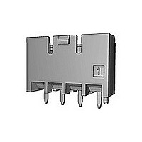
1376444-1 TE Connectivity, 1376444-1 Datasheet

1376444-1
Specifications of 1376444-1
Related parts for 1376444-1
1376444-1 Summary of contents
Page 1
Power Key コネクタの製品 性能、試験方法、品質保証の必要条件を規定している。 適用製品名と型番は附表1の通りである。 2. 参考規格類 以下規格類は本規格中で規定する範囲内に於いて、 本規格の一部を構成する。万一本規格と製品図面の 間に不一致が生じた時は、製品図面を優先して適用する こと。万一本規格と参考規格類の間に不一致が生じた 時は、本規格を優先して適用すること。 2.1 TE規格 A. 114-5292 :取付適用規格 5.0 パワーキイコンタクトの圧着条件 認定試験報告書 B. 501-78274 : 2.2 民間団体規格 A. MIL-STD-202 : 電子電気部品の試験方法 : 電気コネクタ/ソケットの試験手順 B. EIA 364 タイコ ...
Page 2
A. 錫めっき済み 銅合金 (すずめっき 0.8 µm 以上) B. ハウジング : 6/6 ナイロン (ガラス強化) (UL 94 V-0) トラッキングインデックス : 175~250 V C. ダブルロックプレート : 6/6 ナイロン ...
Page 3
A. 定格電圧 300 VAC (但し、ヘッダータイン部ランド間を除く、ランド間寸法 3mm以下の場合は150VACを適用) B. 定格電流 Fig.2参照 C. 使用温度範囲 -30℃~105℃ (但し、温度の上限には、負荷電流によ って生じる温度上昇分を含む) D. 微小定格 1 mV, 1 µA 以上 E. 適用プリント基板 板厚 1.6 mm 穴径 タイン用穴 : 1.25±0.05 (パンチ加工穴) 1.40±0.05 (ドリル加工穴) ボス用穴 : 1.3±0.05 (パンチ、ドリル加工穴) ...
Page 4
No. 試験項目 製品の確認 Test Items 規格値 製品図面とTE 取付適用規格 114-5292 の必要条件に合致していること。 Requirement s 各試験後は、性能に影響する様な腐蝕なき こと。 試験方法 目視により、コネクタの機能上支障を きたす損傷を検査する。 Procedures 電 気 的 性 能 項番 No. 試験項目 総合抵抗(ローレベル) Test Items 規格値 以下 (初期 以下 (終期) Requirements ...
Page 5
No. 試験項目 耐電圧 Test Items 規格値 沿面放電、フラッシュオーバー等がないこと。 Requirements (初期及び終期) リーク電流 以下 試験方法 コネクタ嵌合した状態で隣接コンタクト間 及びコンタクトとハウジングの外郭の間で Procedures 測定。 2.2kVAC 1分間印加測定。 EIA 364-20 項番 No. 試験項目 温度上昇 Test Items 規格値 規定電流を通電して、温度上昇は30℃以下 Requirements 試験方法 通電による温度上昇を測定すること。 測定は、空気の対流の影響を受けない ...
Page 6
No. 試験項目 振動(低周波) Test Items 規格値 振動中 1 µsec. をこえる不連続導通を 生じないこと。 Requirements 20m 以下 (終期) 規格値 振動中 1 µsec. をこえる不連続導通を 生じないこと。 Requirements 20m 以下 (終期) 試験方法 嵌合したコネクタに1.52mmの振幅で、 Procedures 10-55-10Hzに毎分1サイクルの割合で 変化する掃引振動を直交する 三方向軸に各2時間ずつ与えること。 100 mA を通電。 ...
Page 7
No. 試験項目 コネクタ挿抜力 Test Items 規格値 挿入力 9.8N(1.0kg) x 極数以下 Requirements 引抜力 1.47N(0.15kg) x 極数以上 試験方法 ハウジングにコンタクトを組込み操作速度 Procedures 100 mm/分で挿入引抜に要する力を測定。 尚ハウジングのロック機構は取り除いてお く。 EIA 364-13 項番 No. 試験項目 コンタクト装着力 Test Items 規格値 8.82N (0.9 kgf) ...
Page 8
No. 試験項目 コンタクト挿入引抜力 Test Items 規格値 9.8N(1000g) 以下(初回~25 回) 挿入力 Requirements 引抜力 0.34 N(35 g)以上(初回) 0.25N (25 g)以上(25 回) 試験方法 Fig. 9 に規定したゲージを使用して毎分 100 mm の速度で測定 Procedures EIA 364-9 項番 No. 試験項目 圧着部引張強度 Test ...
Page 9
No. 試験項目 ハウジング・ロック強度 Test Items 規格値 29.4N (3.0 kgf) 以上 Requirements 試験方法 コネクタのロック強度を測定 操作速度 : 100 mm/分 Procedures EIA 364-98 項番 No. 試験項目 ポスト保持力 Test Items 規格値 29.4N (3.0 kgf) 以上 Requirements 試験方法 ヘッダー・アセンブリのポストをはんだ付部 ...
Page 10
Environmental Requirements 項番 No. 試験項目 温湿度サイクリング Test Items 規格値 耐電圧 2.2 kVAC 1 分間 (終期) (リーク電流 以下) Requirements 絶縁抵抗 500 M 総合抵抗 試験方法 嵌合したコネクタを 25~65℃, 80~ と-10℃ Procedures ...
Page 11
Environmental Requirements 項番 No. 試験項目 耐熱 Test Items 規格値 以下 (終期 Requirements 試験方法 嵌合したコネクタを 105±2℃ 期間 96 時間さらすこと。 Procedures EIA 364-17 但し、測定は室内放置 3 時間後に行うこと。 項番 No. 試験項目 耐寒性 Test Items 規格値 以下 (終期) ...
Page 12
No. 試験項目 耐アンモニア性 Test Items 規格値 以下 (終期 性能に影響する様な腐食なきこと。 Requirements 試験方法 嵌合したコネクタを 3% アンモニア水溶液 25 ml/l の割合でデシケータに入れこの雰 Procedures 囲気中に 7 時間暴露する。 項番 No. 試験項目 はんだ付け性 Test Items 規格値 90% 以上ぬれていること。 Requirements 試験方法 はんだ温度 はんだ浸漬時間 : 3±0.5 秒 ...
Page 13
Test or Examination 製品の確認検査 Confirmation of Product 総合抵抗 (ローレベル) Termination Resistance (Low Level) 耐電圧 Dielectric withstanding Voltage 絶縁抵抗 Insulation Resistance 温度上昇 Temperature Rising 振動 (低周波) Vibration (Low Frequency) 衝撃 Physical Shock コネクタ挿入力 Connector Mating ...
Page 14
Test or Examination 製品の確認検査 Confirmation of Product 総合抵抗 (ローレベル) Termination Resistance (Low Level) 耐電圧 Dielectric withstanding Voltage 絶縁抵抗 Insulation Resistance 温度上昇 Temperature Rising 振動 (低周波) Vibration (Low Frequency) 衝撃 Physical Shock コネクタ挿入力 Connector Mating Force コネクタ引抜力 ...
Page 15
Kpa 4.2 試験 試料 4.2.1 性能試験に用いる試料は、該当製品図面上の規定事項 に合致したものであること。 また、圧着コンタクトは『5mm ピッチ W-T-B コネクタの 圧着条件 114-5292』に基づいて Fig.6 に示す電線を 圧着した正規の試料であること。 使用電線 4.2.2 性能試験して用いる電線は、Fig. 6 に示す電線にて 行うものとする。 2 計算断面積(mm ) ...
Page 16
Wire-to-Board Termination Type : 測定値から75mmの電線抵抗値を引くこと。 Take the resistance wire only away Fig. 7 Termination Resistance (Low Level) and Temperature Rising Vs. Current Measuring Methods 5mm Power Key Connector 5mm パワー キイ ...
Page 17
Fig. 8 Connector Mounting Methods of Low Frequency Vibration and Physical Shock Tests Rev.E 5mm Power Key Connector 5mm パワー キイ コネクタ Fig. 8 低周波振動、物理的衝撃のコネクタ取付方法 108-5699 ...
Page 18
Fig. 9 Gage Design for Contact Meting/Unmating Force Tests 5mm Power Key Connector 5mm パワー キイ コネクタ Fig. 9 コンタクト挿入引抜力測定用ゲージ 108-5699 Rev. E ...
Page 19
Pos. No. リセ ・ コンタクト (L) □-1376347-□ Receptacle Contact(L) リセ ・ コンタクト (M) □-1376348-□ Receptacle Contact(M) Fig. 10 参照 プラグ ・ ハウジング See Fig. 10 Fig. 10 参照 ヘッダー ・ ハウジング See Fig. 10 Fig. 11 参照 ダブルロックプレート ...


