NL27WZ125USG ON Semiconductor, NL27WZ125USG Datasheet - Page 3
NL27WZ125USG
Manufacturer Part Number
NL27WZ125USG
Description
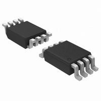
IC BUFFER DL TRI-ST NON-INV US8
Manufacturer
ON Semiconductor
Series
27WZr
Datasheet
1.NL27WZ125USG.pdf
(5 pages)
Specifications of NL27WZ125USG
Logic Type
Buffer/Line Driver, Non-Inverting
Number Of Elements
2
Number Of Bits Per Element
1
Current - Output High, Low
32mA, 32mA
Voltage - Supply
1.65 V ~ 5.5 V
Operating Temperature
-40°C ~ 85°C
Mounting Type
Surface Mount
Package / Case
US8, 8-VSSOP
Package
8US
Logic Family
LCX
Logic Function
Buffer/Line Driver
Number Of Outputs Per Chip
2
Output Type
3-State
Input Signal Type
Single-Ended
Maximum Propagation Delay Time @ Maximum Cl
5.7@3.3V|5@5V ns
Polarity
Non-Inverting
Number Of Channels Per Chip
Dual
Supply Voltage (max)
5.5 V
Supply Voltage (min)
1.65 V
Maximum Operating Temperature
85 C
Mounting Style
SMD/SMT
High Level Output Current
- 32 mA
Input Bias Current (max)
1 uA
Low Level Output Current
32 mA
Maximum Power Dissipation
250 mW
Minimum Operating Temperature
- 40 C
Number Of Lines (input / Output)
3
Propagation Delay Time
5.7 ns @ 3.3 V or 5 ns @ 5 V
Lead Free Status / RoHS Status
Lead free / RoHS Compliant
Other names
NL27WZ125USGOS
NL27WZ125USGOS
NL27WZ125USGOSTR
NL27WZ125USGOS
NL27WZ125USGOSTR
Available stocks
Company
Part Number
Manufacturer
Quantity
Price
Company:

Part Number:
NL27WZ125USG
Manufacturer:
ON
Quantity:
24 000


6. Skew is defined as the absolute value of the difference between the actual propagation delay for any two separate outputs of the same device.
DC ELECTRICAL CHARACTERISTICS
AC ELECTRICAL CHARACTERISTICS
Symbol
Symbol
t
t
V
I
t
t
OSLH
OSHL
t
t
V
t
t
This specification applies to any outputs switching in the same direction, either HIGH−to−LOW (t
guaranteed by design.
V
I
V
OFF
I
PLH
PHL
PZH
PHZ
PZL
PLZ
I
CC
OZ
OH
IN
OL
IH
IL
High−Level Input Voltage
Low−Level Input Voltage
High−Level Output Voltage
V
Low−Level Output Voltage
V
Input Leakage Current
Power Off
Leakage Current
Quiescent Supply Current
3−State Output Leakage
Propagation Delay
AN to YN
(Figures 3 and 4)
Output to Output Skew
(Note 6)
Output Enable Time
(Figures 5, 6 and 7)
Output Enable Time
(Figures 5, 6 and 7)
IN
IN
= V
= V
Parameter
Parameter
IL
IL
or V
IH
R
R
R
R
R
R
R
I
I
I
I
I
I
I
I
I
I
I
I
I
I
V
V
V
V
V
0V v V
OH
OH
OH
OH
OH
OH
OH
OL
OL
OL
OL
OL
OL
OL
L
L
L
L
L
L
L
IN
OUT
IN
IN
IN
= 1 MW
= 1 MW
= 500 W
= 1 MW
= 500 W
= 500 W
= 500 W
= 8 mA
= 12 mA
= 16 mA
= 24 mA
= 32 mA
= 100 mA
= 3 mA
= −8 mA
= −12 mA
= −16 mA
= −24 mA
= −32 mA
= V
= 5.5 V
= V
= V
= 100 mA
= −3 mA
Condition
= 5.5 V
(t
CC
CC
IL
OUT
R
Condition
or V
= t
or GND
or GND
v 5.5 V
F
IH
= 3.0 ns)
C
C
C
C
C
C
C
http://onsemi.com
L
L
L
L
L
L
L
= 15 pF 1.8 $ 0.15
= 15 pF
= 50 pF
= 15 pF
= 50 pF
= 50 pF
= 50 pF
1.65 to 5.5
1.65 to 5.5
2.3 to 5.5
2.3 to 5.5
2.3 to 5.5
1.65
1.65
V
1.65
2.3
2.7
3.0
3.0
4.5
5.5
5.5
(V)
2.3
2.7
3.0
3.0
4.5
3
CC
0
1.8 $ 0.15
1.8 $ 0.15
2.5 $ 0.2
3.3 $ 0.3
5.0 $ 0.5
3.3 $ 0.3
5.0 $ 0.5
2.5 $ 0.2
3.3 $ 0.3
5.0 $ 0.5
2.5 $ 0.2
3.3 $ 0.3
5.0 $ 0.5
V
(V)
CC
V
0.75 V
0.7 V
CC
1.29
Min
1.9
2.2
2.4
2.3
3.8
− 0.1
CC
CC
Min
2.0
1.0
0.8
1.2
0.5
0.8
3.0
1.8
1.2
0.8
2.5
1.5
0.8
0.3
T
A
1.52
0.08
0.20
0.22
0.28
0.38
0.42
= 255C
Typ
V
T
2.1
2.4
2.7
2.5
4.0
CC
A
Typ
= 255C
OSHL
0.25 V
0.3 V
$0.1
$0.5
Max
0.24
0.55
0.55
0.1
0.3
0.4
0.4
1.0
1.0
Max
) or LOW−to−HIGH (t
7.5
5.2
5.7
4.5
5.0
1.0
0.8
8.5
6.2
5.5
8.0
5.7
4.7
12
14
12
CC
CC
−555C v T
−555C v T
0.75 V
V
0.7 V
CC
1.29
Min
Min
1.9
2.2
2.4
2.3
3.8
2.0
1.0
0.8
1.2
0.5
0.8
3.0
1.8
1.2
0.8
2.5
1.5
0.8
0.3
−0.1
CC
CC
A
A
0.25 V
v 1255C
v 1255C
0.3 V
OSLH
$1.0
Max
0.24
0.55
0.55
Max
$5
0.1
0.3
0.4
0.4
5.5
6.0
4.8
5.3
1.0
0.8
9.0
6.5
5.8
8.5
6.0
5.0
10
10
13
15
13
8
); parameter
CC
CC
Unit
Unit
mA
mA
mA
mA
ns
ns
ns
ns
V
V
V
V
Related parts for NL27WZ125USG
Image
Part Number
Description
Manufacturer
Datasheet
Request
R

Part Number:
Description:
ON Semiconductor [VOLTAGE REGULATOR]
Manufacturer:
ON Semiconductor
Datasheet:
Part Number:
Description:
357-036-542-201 CARDEDGE 36POS DL .156 BLK LOPRO
Manufacturer:
ON Semiconductor
Datasheet:
Part Number:
Description:
357-036-542-201 CARDEDGE 36POS DL .156 BLK LOPRO
Manufacturer:
ON Semiconductor
Datasheet:
Part Number:
Description:
357-036-542-201 CARDEDGE 36POS DL .156 BLK LOPRO
Manufacturer:
ON Semiconductor
Datasheet:
Part Number:
Description:
357-036-542-201 CARDEDGE 36POS DL .156 BLK LOPRO
Manufacturer:
ON Semiconductor
Datasheet:
Part Number:
Description:
357-036-542-201 CARDEDGE 36POS DL .156 BLK LOPRO
Manufacturer:
ON Semiconductor
Datasheet:
Part Number:
Description:
357-036-542-201 CARDEDGE 36POS DL .156 BLK LOPRO
Manufacturer:
ON Semiconductor
Datasheet:
Part Number:
Description:
357-036-542-201 CARDEDGE 36POS DL .156 BLK LOPRO
Manufacturer:
ON Semiconductor
Datasheet:
Part Number:
Description:
357-036-542-201 CARDEDGE 36POS DL .156 BLK LOPRO
Manufacturer:
ON Semiconductor
Datasheet:
Part Number:
Description:
357-036-542-201 CARDEDGE 36POS DL .156 BLK LOPRO
Manufacturer:
ON Semiconductor
Datasheet:
Part Number:
Description:
357-036-542-201 CARDEDGE 36POS DL .156 BLK LOPRO
Manufacturer:
ON Semiconductor
Datasheet:
Part Number:
Description:
Manufacturer:
ON Semiconductor
Datasheet:
Part Number:
Description:
Manufacturer:
ON Semiconductor
Datasheet:
Part Number:
Description:
Manufacturer:
ON Semiconductor
Datasheet: