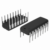
MC14521BCPG ON Semiconductor, MC14521BCPG Datasheet - Page 6

MC14521BCPG
Manufacturer Part Number
MC14521BCPG
Description
IC OSCILLATOR 24STAGE 16DIP
Manufacturer
ON Semiconductor
Series
4000Br
Specifications of MC14521BCPG
Logic Type
Divide-by-2
Number Of Elements
1
Number Of Bits Per Element
24
Count Rate
12MHz
Trigger Type
Negative Edge
Voltage - Supply
3 V ~ 18 V
Operating Temperature
-55°C ~ 125°C
Mounting Type
Through Hole
Package / Case
16-DIP (0.300", 7.62mm)
Logic Family
MC145
Mounting Style
Through Hole
Circuit Type
Low-Power Schottky
Current, Supply
600 μA
Function Type
24-Stages
Logic Function
Frequency Divider
Package Type
PDIP-16
Special Features
Resettable
Temperature, Operating, Range
-55 to +125 °C
Voltage, Supply
3 to 18 VDC
Lead Free Status / RoHS Status
Lead free / RoHS Compliant
Direction
-
Reset
-
Timing
-
Lead Free Status / Rohs Status
Lead free / RoHS Compliant
Other names
MC14521BCPGOS
Available stocks
Company
Part Number
Manufacturer
Quantity
Price
Part Number:
MC14521BCPG
Manufacturer:
ON/安森美
Quantity:
20 000
Î Î Î Î Î Î Î Î Î Î Î Î Î Î Î Î Î Î Î Î Î Î Î Î Î Î Î Î Î Î Î Î Î
Î Î Î Î Î Î Î Î Î Î Î Î Î Î Î Î Î Î Î Î Î Î Î Î Î Î Î Î Î Î Î Î Î
FUNCTIONAL TEST SEQUENCE
for the reduction of test time required to exercise all
24 counter stages. This test function divides the
counter into three 8−stage sections, and 255
counts are loaded in each of the 8−stage sections
in parallel. All flip−flops are now at a logic “1”. The
counter is now returned to the normal 24−stages in
series configuration. One more pulse is entered into
Input 2 (In 2) which will cause the counter to ripple
from an all “1” state to an all “0” state.
-4.0
-8.0
-12
-16
A test function (see Figure 8) has been included
8.0
4.0
0
-55
R
C = 1000 pF
TC
= 56 kW,
-25
T
Figure 7. RC Oscillator Circuit
A
R
, AMBIENT TEMPERATURE (°C), DEVICE ONLY
Figure 5. RC Oscillator Stability
S
{
0
C
R
R
S
S
= 0, f = 10.15 kHz @ V
= 120 kW, f = 7.8 kHz @ V
R
TC
25
IN 1
IN 2
R
V
V
DD
SS
OUT 1
OUT 2
10 V
V
5.0 V
Q18
Q19
Q20
Q21
Q22
Q23
Q24
DD
50
V
V
V
= 15 V
DD
SS
DD
DD
′
′
= 10 V, T
DD
75
= 10 V, T
TEST CIRCUIT
Reset
A
FIGURE 7
= 25°C
1
0
A
Inputs
100
= 25°C
http://onsemi.com
In 2
0
1
0
1
−
−
−
1
0
0
1
1
0
125
Out 2
6
0
1
0
1
−
−
−
1
0
0
0
0
1
100
5.0
2.0
1.0
0.5
0.2
0.1
50
20
10
GND
V
V
0.0001
1.0 k
SS
DD
GENERATOR
Outputs
f AS A FUNCTION
′
PULSE
(R
(R
TC
GND
V
Figure 6. RC Oscillator Frequency as a
V
S
OF C
DD
DD
= 120 k)
= 56 kW)
′
Figure 8. Functional Test Circuit
Q18
Q24
thru
Function of R
0
1
1
1
1
1
0
R
0.001
10 k
TC
C, CAPACITANCE (mF)
, RESISTANCE (OHMS)
Counter is in three 8−stage sections
in parallel mode Counter is reset. In 2
and Out 2 are connected together.
First “0” to “1” transition on In 2,
Out 2 node.
255 “0” to “1” transitions are clocked
into this In 2, Out 2 node.
The 255th “0” to “1” transition.
Counter converted back to 24−stages
in series mode.
Out 2 converts back to an output.
Counter ripples from an all “1” state
to an all “0” stage.
V
DD
TC
= 10 V
IN 1
IN 2
R
Comments
and C
V
100 k
V
0.01
DD
SS
OUT 1
OUT 2
f AS A FUNCTION
(C = 1000 pF)
Q18
Q19
Q20
Q21
Q22
Q23
Q24
(R
TEST CIRCUIT
V
OF R
V
S
SS
DD
FIGURE 7
≈ 2R
′
TC
TC
)
1.0 m
0.1


