NL27WZ14DFT2 ON Semiconductor, NL27WZ14DFT2 Datasheet

IC INVERTER DUAL SCHMITT SOT363

NL27WZ14DFT2

Manufacturer Part Number
NL27WZ14DFT2
Description
IC INVERTER DUAL SCHMITT SOT363
Manufacturer
ON Semiconductor
Series
7WZr
Datasheet

Specifications of NL27WZ14DFT2

Logic Type
Inverter with Schmitt Trigger
Number Of Inputs
1
Number Of Circuits
2
Current - Output High, Low
32mA, 32mA
Voltage - Supply
2.3 V ~ 5.5 V
Operating Temperature
-55°C ~ 125°C
Mounting Type
Surface Mount
Package / Case
SC-70-6, SC-88, SOT-363
Lead Free Status / RoHS Status
Contains lead / RoHS non-compliant
Other names
NL27WZ14DFT2OSCT

Available stocks

Company
Part Number
Manufacturer
Quantity
Price
Part Number:
NL27WZ14DFT2
Manufacturer:
ON/安森美
Quantity:
20 000
Part Number:
NL27WZ14DFT2G
Manufacturer:
ON
Quantity:
45 000
Part Number:
NL27WZ14DFT2G
Manufacturer:
NXP
Quantity:
1 200
Part Number:
NL27WZ14DFT2G
Manufacturer:
ON/安森美
Quantity:
20 000
Part Number:
NL27WZ14DFT2G
0
Company:
Part Number:
NL27WZ14DFT2G
Quantity:
4 500
Company:
Part Number:
NL27WZ14DFT2G
Quantity:
8 977
Company:
Part Number:
NL27WZ14DFT2G
Quantity:
90 000
NL27WZ14
Dual Schmitt-Trigger
Inverter
Schmitt−Trigger inputs operating from a 1.65 to 5.5 V supply.
the inputs have hysteresis and, with its Schmitt trigger function, the
NL27WZ14 can be used as a line receiver which will receive slow
input signals. The NL27WZ14 is capable of transforming slowly
changing input signals into sharply defined, jitter−free output signals.
In addition, it has a greater noise margin than conventional inverters.
The NL27WZ14 has hysteresis between the positive−going and the
negative−going input thresholds (typically 1 V) which is determined
internally by transistor ratios and is essentially insensitive to
temperature and supply voltage variations.
Features
© Semiconductor Components Industries, LLC, 2009
January, 2009 − Rev. 10
The NL27WZ14 is a high performance dual inverter with
Pin configuration and function are the same as the NL27WZ04, but
with V
Power Requirements
Designed for 1.65 V to 5.5 V V
Over Voltage Tolerant Inputs and Outputs
LVTTL Compatible − Interface Capability with 5 V TTL Logic
LVCMOS Compatible
24 mA Balanced Output Sink and Source Capability
Near Zero Static Supply Current Substantially Reduces System
Current Drive Capability is 24 mA at the Outputs
Chip Complexity: FET = 72
Pb−Free Packages are Available
IN A1
IN A2
GND
IN A1
IN A2
CC
= 3 V
Figure 1. Pinout
1
2
3
Figure 2. Logic Symbol
1
1
(Top View)
CC
Operation
6
5
4
OUT Y1
OUT Y2
OUT Y1
V
OUT Y2
CC
1
TSOP−6/SOT−23−6/SC59−6
See detailed ordering and shipping information in the package
dimensions section on page 2 of this data sheet.
SC−88/SOT−363/SC70−6
*Date Code orientation and/or position may vary
depending upon manufacturing location.
(Note: Microdot may be in either location)
Pin
1
2
3
4
5
6
6
CASE 419B
CASE 318G
DF SUFFIX
DT SUFFIX
A Input
6
ORDERING INFORMATION
H
L
MA
M
G
http://onsemi.com
PIN ASSIGNMENT
FUNCTION TABLE
1
1
= Device Marking
= Date Code*
= Pb−Free Package
Publication Order Number:
Function
OUT Y2
OUT Y1
IN A2
IN A1
GND
V
6
1
CC
6
1
DIAGRAMS
Y Output
MARKING
NL27WZ14/D
MA M G
H
L
MA M G
G
G

Related parts for NL27WZ14DFT2

NL27WZ14DFT2 Summary of contents

Page 1

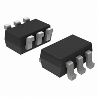
NL27WZ14 Dual Schmitt-Trigger Inverter The NL27WZ14 is a high performance dual inverter with Schmitt−Trigger inputs operating from a 1.65 to 5.5 V supply. Pin configuration and function are the same as the NL27WZ04, but the inputs have hysteresis and, with ...

Page 2

... Operating Free−Air Temperature A Dt/DV Input Transition Rise or Fall Rate ORDERING INFORMATION Device NL27WZ14DFT2 NL27WZ14DFT2G NL27WZ14DTT1 NL27WZ14DTT1G †For information on tape and reel specifications, including part orientation and tape sizes, please refer to our Tape and Reel Packaging Specifications Brochure, BRD8011/D. Characteristics Output LOW State (Note 1) ...

Page 3

DC ELECTRICAL CHARACTERISTICS Symbol Parameter Condition V ) Positive Input T Threshold Voltage V * Negative Input T Threshold Voltage V Input Hysteresis H Voltage V High−Level I = −100 Output Voltage ...

Page 4

50% t PLH Y 50 Figure 3. Switching Waveforms Figure 5. Typical Input Threshold out (a) A Schmitt−Trigger Squares Up Inputs With Slow Rise ...

Page 5

... 0.0197 0.40 0.0157 *For additional information on our Pb−Free strategy and soldering details, please download the ON Semiconductor Soldering and Mounting Techniques Reference Manual, SOLDERRM/D. PACKAGE DIMENSIONS SC−88/SC70−6/SOT−363 CASE 419B−02 ISSUE W NOTES: 1. DIMENSIONING AND TOLERANCING PER ANSI Y14.5M, 1982. ...

Page 6

... Pb−Free strategy and soldering details, please download the ON Semiconductor Soldering and Mounting Techniques Reference Manual, SOLDERRM/D. ON Semiconductor and are registered trademarks of Semiconductor Components Industries, LLC (SCILLC). SCILLC reserves the right to make changes without further notice to any products herein ...

Related keywords