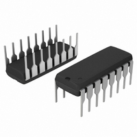
MC14532BCPG ON Semiconductor, MC14532BCPG Datasheet - Page 6

MC14532BCPG
Manufacturer Part Number
MC14532BCPG
Description
IC ENCODER PRIORITY 8BIT 16DIP
Manufacturer
ON Semiconductor
Series
4000Br
Type
Priority Encoderr
Specifications of MC14532BCPG
Circuit
1 x 8:3
Independent Circuits
1
Voltage Supply Source
Dual Supply
Voltage - Supply
3 V ~ 18 V
Operating Temperature
-55°C ~ 125°C
Mounting Type
Through Hole
Package / Case
16-DIP (0.300", 7.62mm)
Product
Decoders, Encoders, Multiplexers & Demultiplexers
Logic Family
MC145
Number Of Bits
8
Number Of Lines (input / Output)
9.0 / 4.0
Propagation Delay Time
600 ns at 5 V, 340 ns at 10 V, 220 ns at 15 V
Supply Voltage (max)
18 V
Supply Voltage (min)
3 V
Maximum Operating Temperature
+ 125 C
Minimum Operating Temperature
- 55 C
Mounting Style
SMD/SMT
Number Of Input Lines
9.0
Number Of Output Lines
4.0
Circuit Type
Low-Power Schottky
Current, Supply
600 μA
Function Type
1-Channel, 8-Bits
Logic Function
Encoder
Logic Type
CMOS
Package Type
PDIP-16
Special Features
Binary
Temperature, Operating, Range
-55 to +125 °C
Voltage, Supply
3 to 18 VDC
No. Of Outputs
5
Supply Voltage Range
3V To 18V
Logic Case Style
DIP
No. Of Pins
16
Operating Temperature Range
-55°C To +125°C
Filter Terminals
Through Hole
Rohs Compliant
Yes
Family Type
4000 CMOS
Lead Free Status / RoHS Status
Lead free / RoHS Compliant
Current - Output High, Low
-
Lead Free Status / Rohs Status
Lead free / RoHS Compliant
Other names
MC14532BCPGOS
Available stocks
Company
Part Number
Manufacturer
Quantity
Price
Company:
Part Number:
MC14532BCPG
Manufacturer:
SFIC
Quantity:
101
DIGITAL TO ANALOG CONVERSION
inputs of the MC14512 with the most significant bit at X7
and the least significant bit at X0. A clock input of up to
2.5 MHz (at V
A compromise between I
tween N and P−channel outputs gives a value of R of 33 kW.
In order to filter out the switching frequencies, RC should
be about 1.0 ms (if R = 33 kW, C [ 0.03 mF). The analog 3.0
dB bandwidth would then be dc to 1.0 kHz.
ANALOG TO DIGITAL CONVERSION
MC1710. A digital eight−bit word known to represent a dig-
itized level less than the analog input is applied to the
MC14512 as in the D to A conversion. The word is increm-
ented at rates sufficient to allow steady state to be reached
between incrementations (i.e. 3.0 ms). The output of the
MC1710 will change when the digital input represents the
first digitized level above the analog input. This word is the
digital representation of the analog word.
The digital eight−bit word to be converted is applied to the
An analog signal is applied to the analog input of the
V
DD
DD
= 10 V) is applied to the MC14520B.
D15 D14 D13 D12 D11 D10
E
D7
Q3
in
GS
bias
D6
for the MC1710 and DR be-
Figure 6. Digital to Analog and Analog to Digital Converter
D5
Figure 5. Two MC14532B’s Cascaded for 4−Bit Output
D4
D3
Q2
Q2
D2
Q1
D9
D1
Q1
http://onsemi.com
Q0
D8
D0
E
out
MC14532B
CLOCK
INPUT
Q0
6
V
DD
3/4 MC14071B
E
D7
D7
E
in
D0 D1 D2 D3 D4 D5 D6 D7
Q1
STOP
WORD
INCREMENTATION
in
C
D6
D6
1/2 MC14520B
Q2
D5
D5
E
V
D4
D4
DD
Q3
Q2
Q1
D3
D3
Q2
Q0
Q4
R
D2
D2
V
SS
Q1
MC1710
ANALOG
D1
D1
INPUT
A
B
C
Q0
X7 X6 X5 X4 X3 X2 X1 X0
Q1
C
DIGITAL INPUT/OUTPUT
D0
D0
E
TO BE CONVERTED
out
1/2 MC14520B
8−BIT WORD
Q2
MC14512
Z
E
E
WITH D
out
R
Q3
C
= 1"
in
ANALOG
OUTPUT
= 0"
Q4
R


