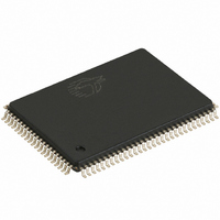
CY7C1350G-133AXC Cypress Semiconductor Corp, CY7C1350G-133AXC Datasheet

CY7C1350G-133AXC
Specifications of CY7C1350G-133AXC
CY7C1350G-133AXC
Available stocks
Related parts for CY7C1350G-133AXC
CY7C1350G-133AXC Summary of contents
Page 1
... The CY7C1350G burst SRAM designed specifically to support unlimited true back-to-back read/write operations without the insertion of wait states. The CY7C1350G is equipped with the advanced No Bus Latency™ (NoBL™) logic required to enable consecutive read/write operations with data being transferred on every clock cycle. This feature dramatically improves the throughput of the SRAM, especially in systems that require frequent write/read transitions ...
Page 2
... Switching Waveforms .................................................... 11 NOP, STALL, and DESELECT Cycles ...................... 12 ZZ Mode Timing ........................................................ 12 Ordering Information ...................................................... 13 Ordering Code Definitions ......................................... 13 Package Diagrams .......................................................... 14 Acronyms ........................................................................ 16 Document Conventions ................................................. 16 Units of Measure ....................................................... 16 Document History Page ................................................. 17 Sales, Solutions, and Legal Information ...................... 18 Worldwide Sales and Design Support ....................... 18 Products .................................................................... 18 PSoC Solutions ......................................................... 18 CY7C1350G Page [+] Feedback ...
Page 3
... V DDQ DDQ BYTE DDQ DQP D Document Number: 38-05524 Rev. *I 250 MHz 200 MHz 166 MHz 2.6 2.8 3.5 325 265 240 100-pin TQFP Pinout CY7C1350G CY7C1350G 133 MHz 100 MHz Unit 4.0 4.5 ns 225 205 DQP DDQ BYTE DDQ DDQ 60 V ...
Page 4
... Document Number: 38-05524 Rev. *I 119-ball BGA Pinout NC/18M ADV/ DQP NC/ CLK CEN DQP MODE NC/72M Description are fed to the two-bit burst counter. [1:0] to select/deselect the device select/deselect the device select/deselect the device. 2 CY7C1350G DDQ DQP DDQ DDQ DDQ DQP NC/288M NC/36M DDQ Page [+] Feedback ...
Page 5
... Burst Read Accesses The CY7C1350G has an on-chip burst counter that allows the user the ability to supply a single address and conduct up to four reads without reasserting the address inputs. ADV/LD must be ...
Page 6
... OE. Burst Write Accesses The CY7C1350G has an on-chip burst counter that allows the user the ability to supply a single address and conduct up to four write operations without reasserting the address inputs. ADV/LD ...
Page 7
... Table only lists a partial listing of the byte write combinations. Any combination of BW Document Number: 38-05524 Rev ADV/ [9, 10, 11 Test Conditions 0 > 0 > < 0.2 V This parameter is sampled This parameter is sampled is valid. Appropriate write will be done on which byte write is active. X CY7C1350G OE CEN CLK L-H Tri-state L-H Tri-state L-H — Tri-state ...
Page 8
... MHz = Max, device deselected, All speeds 0 > V – 0 DDQ /2), undershoot: V (AC) > –2 V (Pulse width less than t CYC IL (min) within 200 ms. During this time V < V and CY7C1350G + 0 Ambient DDQ Temperature ( °C to +70 °C 3.3 V – 5% 2.5 V – 10 40 °C to +85 °C DD ...
Page 9
... R = 317 3 OUTPUT DDQ GND 351 INCLUDING JIG AND (b) SCOPE R = 1667 2 DDQ OUTPUT GND =1538 INCLUDING JIG AND (b) SCOPE CY7C1350G Min Max Unit – 105 mA – – – – – 119 BGA 100 TQFP Unit Max ...
Page 10
... V. DDQ is the time that the power needs to be supplied above V and t is less than t to eliminate bus contention between SRAMs when sharing the same OELZ CHZ CLZ CY7C1350G –166 –133 –100 Max Min Max Min Max Unit 1 – 1 – ...
Page 11
... DOH CLZ D(A2) D(A2+1) Q(A3) t OEHZ READ READ BURST Q(A3) Q(A4) READ Q(A4+1) DON’T CARE UNDEFINED is LOW. When CE is HIGH HIGH CY7C1350G OEV CHZ Q(A4) Q(A4+1) D(A5) Q(A6) t DOH t OELZ WRITE READ WRITE DESELECT D(A5) Q(A6) D(A7) is LOW HIGH Page ...
Page 12
... A3 A4 D(A1) Q(A2) Q(A3) STALL READ WRITE STALL Q(A3) D(A4) DON’T CARE UNDEFINED High-Z DON’T CARE is LOW. When CE is HIGH HIGH CY7C1350G CHZ D(A4) Q(A5) NOP READ DESELECT CONTINUE Q(A5) DESELECT t ZZREC t RZZI DESELECT or READ Only is LOW HIGH Page ...
Page 13
... Speed Package (MHz) Ordering Code Diagram 133 CY7C1350G-133AXC 51-85050 100-pin Thin Quad Flat Pack (14 × 20 × 1.4 mm) Pb-free CY7C1350G-133AXI 51-85050 100-pin Thin Quad Flat Pack (14 × 20 × 1.4 mm) Pb-free CY7C1350G-133BGXC 51-85050 100-pin Thin Quad Flat Pack (14 × 20 × 1.4 mm) Pb-free 200 CY7C1350G-200AXC 51-85050 100-pin Thin Quad Flat Pack (14 × ...
Page 14
... Package Diagrams Document Number: 38-05524 Rev. *I 100-pin TQFP (14 × 20 × 1.4 mm), 51-85050 CY7C1350G 51-85050 *C Page [+] Feedback ...
Page 15
... Package Diagrams (continued) 119-ball BGA (14 × 22 × 2.4 mm), 51-85115 Document Number: 38-05524 Rev. *I CY7C1350G 51-85115 *C Page [+] Feedback ...
Page 16
... TQFP thin quad flat pack WE write enable Document Number: 38-05524 Rev. *I Document Conventions Units of Measure Symbol Unit of Measure ns nano seconds V Volts µA micro Amperes mA milli Amperes ms milli seconds MHz Mega Hertz pF pico Farad W Watts °C degree Celcius CY7C1350G Page [+] Feedback ...
Page 17
... Document History Page Document Title: CY7C1350G 4-Mbit (128 K x 36) Pipelined SRAM with NoBL™ Architecture Document Number: 38-05524 Orig. of REV. ECN NO. Issue Date Change Description of Change ** 224380 See ECN RKF *A 276690 See ECN VBL *B 332895 See ECN SYT *C 351194 See ECN ...
Page 18
... Document Number: 38-05524 Rev. *I ZBT is a trademark of Integrated Device Technology, Inc. NoBL and No Bus Latency are trademarks of Cypress Semiconductor Corporation. All products and company names mentioned in this document may be the trademarks of their respective holders. cypress.com/go/plc Revised March 31, 2011 CY7C1350G PSoC Solutions psoc.cypress.com/solutions PSoC 1 | ...


