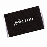
MT29F8G08BAAWP:A TR Micron Technology Inc, MT29F8G08BAAWP:A TR Datasheet - Page 39

MT29F8G08BAAWP:A TR
Manufacturer Part Number
MT29F8G08BAAWP:A TR
Description
IC FLASH 8GBIT 48TSOP
Manufacturer
Micron Technology Inc
Datasheet
1.MT29F16G08DAAWP-ETA_TR.pdf
(81 pages)
Specifications of MT29F8G08BAAWP:A TR
Format - Memory
FLASH
Memory Type
FLASH - Nand
Memory Size
8G (1G x 8)
Interface
Parallel
Voltage - Supply
2.7 V ~ 3.6 V
Operating Temperature
0°C ~ 70°C
Package / Case
48-TSOP
Lead Free Status / RoHS Status
Lead free / RoHS Compliant
Speed
-
TWO-PLANE PROGRAM PAGE 80h-11h-80h-10h
Figure 28:
PDF: 09005aef81b80e13/Source: 09005aef81b80eac
4gb_nand_m40a__2.fm - Rev. B 2/07 EN
R/B#
I/Ox
80h
TWO-PLANE PROGRAM PAGE Operation
1st plane address
Address (5 cycles)
The TWO-PLANE PROGRAM PAGE (80h-11h-80h-10h) operation is similar to the
PROGRAM PAGE (80h-10h) operation. It programs two pages of data from the data
registers to the Flash arrays. The pages must be programmed to different planes on the
same die. Within a block, the pages must be programmed consecutively from the least
significant to most significant page address. Random page programming within a block
is prohibited. The first-plane address and the second-plane address must meet the two-
plane addressing requirements (see “Two-Plane Addressing” on page 35).
To begin the TWO-PLANE PROGRAM PAGE operation, write the 80h command to the
command register; write 5 ADDRESS cycles for the first plane; then write the data. Serial
data is loaded on consecutive WE# cycles starting at the given address. Next, write the
11h command. The 11h command is a “dummy” command that informs the control
logic that the first set of data for the first plane is complete. No programming of the
NAND Flash array occurs. R/B# goes LOW for
STATUS (70h) command also indicates that the device is ready when status register bit 6
is set to “1.” The only valid commands during
RESET (FFh).
After
ADDRESS cycles for the second plane; then write the data. The PROGRAM (10h)
command is written after the second-plane data input is complete.
After the 10h command is written, the control logic automatically executes the proper
algorithm and controls all the necessary timing to program and verify the operations to
both planes. WRITE verification only detects “1s” that are not successfully written
to “0s.”
R/B# goes LOW for the duration of the array programming time (
programming and verification are complete, R/B# returns HIGH. The READ STATUS
(70h) command also indicates that the device is ready when status register bit 6 is set to
“1.” The only valid commands during
MULTIPLE-DIE READ STATUS (78h), and RESET (FFh).
When the device is ready, if the READ STATUS (70h) command indicates an error in the
operation (status register bit 0 = 1), use the TWO-PLANE/MULTIPLE-DIE READ
STATUS (78h) command twice—once for each plane—to determine which plane opera-
tion failed.
During serial data input for either plane, the RANDOM DATA INPUT (85h) command
can be used any number of times to change the column address within that plane. For
details on this command, see “RANDOM DATA INPUT 85h” on page 27. Figure 28 shows
TWO-PLANE PROGRAM PAGE operation.
Data
t
DBSY, write the 80h (or 81h) command to the command register; write 5
input
11h
t DBSY
(or 81h)
80h
2nd plane address
39
Address (5 cycles)
4Gb, 8Gb, and 16Gb x8 NAND Flash Memory
t
PROG are READ STATUS (70h), TWO-PLANE/
Micron Technology, Inc., reserves the right to change products or specifications without notice.
Data
t
t
DBSY, then returns HIGH. The READ
DBSY are READ STATUS (70h) and
input
10h
Command Definitions
t PROG
©2006 Micron Technology, Inc. All rights reserved.
t
PROG). When
70h
Status


