DS1248WP-120IND Maxim Integrated Products, DS1248WP-120IND Datasheet
DS1248WP-120IND
Specifications of DS1248WP-120IND


Related parts for DS1248WP-120IND


DS1248WP-120IND Summary of contents
Page 1
... Pin-for-Pin Compatible with DS1244P and DS1251P PowerCap is a registered trademark of Maxim Integrated Products, Inc. Note: Some revisions of this device may incorporate deviations from published specifications known as errata. Multiple revisions of any device may be simultaneously available through various sales channels. For information about device errata, click here: www.maxim-ic.com/errata. ...
Page 2
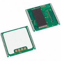
... DS1248W-120IND+ -40°C to +85°C DS1248WP-120+ 0°C to +70°C DS1248WP-120IND+ -40°C to +85°C + Denotes a lead(Pb)-free/RoHS-compliant device. * DS9034PCX (PowerCap) required. Must be ordered separately “IND” is located in the lower right-hand corner of the label. *** The top mark will include a “+” symbol on lead-free devices. ...
Page 3
PIN DESCRIPTION PIN NAME EDIP PowerCap RST A16 3 32 A14 4 30 A12 ...
Page 4
RAM READ MODE The DS1248 executes a read cycle whenever WE (write enable) is inactive (high) and CE (chip enable) is active (low). The unique address specified by the 17 address inputs (A0–A16) defines which of the 128k bytes of ...
Page 5
... Data transfer to and from the timekeeping function is accomplished with a serial bit stream under control of chip enable, output enable, and write enable. Initially, a read cycle to any memory location using the CE and OE control of the phantom clock starts the pattern recognition sequence by moving a pointer to the first bit of the 64-bit comparison register ...
Page 6
Figure 1. Phantom Clock Register Definition NOTE: THE PATTERN RECOGNITION IN HEX IS C5, 3A, A3, 5C, C5, 3A, A3, 5C. THE ODDS OF THIS PATTERN BEING ACCIDENTALLY DUPLICATED AND CAUSING INADVERTENT ENTRY TO THE PHANTOM CLOCK IS LESS THAN ...
Page 7
Figure 2. Phantom Clock Register Definition AM/PM/12/24-MODE Bit 7 of the hours register is defined as the 12-hour or 24-hour mode-select bit. When high, the 12-hour mode is selected. In the 12-hour mode, bit 5 is the AM/PM bit with ...
Page 8
ZERO BITS Registers and 6 contain one or more bits, which will always read logic 0. When writing these locations, either a logic acceptable. BATTERY LONGEVITY The DS1248 has a lithium ...
Page 9
ABSOLUTE MAXIMUM RATINGS Voltage Range on Any Pin Relative to Ground……………………………………………..-0.3V to +6.0V Storage Temperature Range.………………………………………………40ºC to +85ºC (noncondensing) Soldering Temperature..………………………………………...+260C for 10 seconds (EDIP) (Note 13); This is a stress rating only and functional operation of the device at ...
Page 10
... Write Protection Voltage Battery Switchover Voltage CAPACITANCE (T = +25C) A PARAMETER Input Capacitance Input/Output Capacitance MEMORY AC ELECTRICAL CHARACTERISTICS Over the Operating Range (5V) PARAMETER Read Cycle Time Access Time OE to Output Valid CE to Output Valid Output Active Output High-Z from Deselection Output Hold from Address Change ...
Page 11
PHANTOM CLOCK AC ELECTRICAL CHARACTERISTICS Over the Operating Range (5V) PARAMETER Read Cycle Time CE Access Time OE Access Time CE to Output Low Output Low Output High Output High-Z Read Recovery Write Cycle ...
Page 12
... MEMORY AC ELECTRICAL CHARACTERISTICS Over the Operating Range (3.3V) PARAMETER Read Cycle Time Access Time OE to Output Valid CE to Output Valid Output Active Output High-Z from Deselection Output Hold from Address Change Write Cycle Time Write Pulse Width Address Setup Time Write Recovery Time ...
Page 13
... V ) PF(MIN Slew from PF(MAX PF(MIN after Power- +25°C) A PARAMETER Expected Data-Retention Time Warning: Under no circumstances are negative undershoots, of any amplitude, allowed when device is in battery-backup mode. MEMORY READ CYCLE (Note 1) SYMBOL MIN TYP 300 1.5 REC SYMBOL MIN TYP MAX UNITS NOTES ...
Page 14
... MEMORY WRITE CYCLE 1 (Notes 2, 6, and 7) MEMORY WRITE CYCLE 2 (Notes 2 and ...
Page 15
RESET FOR PHANTOM CLOCK READ CYCLE TO PHANTOM CLOCK WRITE CYCLE TO PHANTOM CLOCK ...
Page 16
POWER-DOWN/POWER-UP CONDITION (5V) POWER-DOWN/POWER-UP CONDITION (3.3V ...
Page 17
AC TEST CONDITIONS Output Load: 50pF + 1TTL Gate Input Pulse Levels Timing Measurement Reference Levels Input: 1.5V Output: 1.5V Input Pulse Rise and Fall Times: 5ns NOTES high for a read cycle. 2) ...
Page 18
... No circuit patent licenses are implied. Maxim/Dallas Semiconductor reserves the right to change the circuitry and specifications without notice at any time The Maxim logo is a registered trademark of Maxim Integrated Products, Inc. The Dallas logo is a registered trademark of Dallas Semiconductor. DS1248/DS1248P 1024k NV SRAM with Phantom Clock DOCUMENT NO ...