LNK520PN Power Integrations, LNK520PN Datasheet - Page 2
LNK520PN
Manufacturer Part Number
LNK520PN
Description
IC SWIT OCP CV/CC HV 8DIP
Manufacturer
Power Integrations
Series
LinkSwitch®r
Datasheet
1.LNK520PN.pdf
(20 pages)
Specifications of LNK520PN
Output Isolation
Isolated
Frequency Range
24 ~ 49.5kHz
Voltage - Output
700V
Power (watts)
4W
Operating Temperature
-40°C ~ 150°C
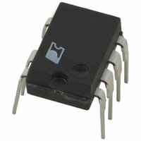
Package / Case
8-DIP (0.300", 7.62mm), 7 Leads
Output Voltage
5.6 V
Input / Supply Voltage (max)
265 VAC
Input / Supply Voltage (min)
85 VAC
Duty Cycle (max)
80 %
Switching Frequency
42 KHz
Supply Current
0.75 mA
Operating Temperature Range
- 40 C to + 150 C
Mounting Style
Through Hole
For Use With
596-1006 - KIT DESIGN ACCELERATOR ADAPTER596-1001 - KIT DESIGN ACCELERATOR ADAPTER
Lead Free Status / RoHS Status
Lead free / RoHS Compliant
Other names
596-1033-5
Available stocks
Company
Part Number
Manufacturer
Quantity
Price
Company:

Part Number:
LNK520PN
Manufacturer:
POWER
Quantity:
15 000
Part Number:
LNK520PN
Manufacturer:
POWER
Quantity:
20 000


Figure 2. Block Diagram.
Pin Functional Description
DRAIN (D) Pin:
Power MOSFET drain connection. Provides internal operating
current for start-up. Internal current limit sense point for drain
current.
CONTROL (C) Pin:
Error amplifier and feedback current input pin for duty cycle
and current limit control. Internal shunt regulator connection
to provide internal bias current during normal operation. It is
also used as the connection point for the supply bypass and
auto-restart/compensation capacitor.
SOURCE (S) Pin:
Output MOSFET source connection for high voltage power
return. Primary side control circuit common and reference
point.
2
CONTROL
LNK520
E
2/05
I DCS
R E
Z C
I
SHUNT REGULATOR/
FB
ERROR AMPLIFIER
OSCILLATOR
CLOCK
V C
D MAX
SAW
+
-
5.6 V
COMPARATOR
5.6 V
4.7 V
PW M
+
-
AUTO-RESTART
SHUTDOWN/
+
-
FREQUENCY
OPERATION
LOW
HYSTERETIC
SHUTDOWN
THERMAL
0
1
Figure 3. Pin Configuration.
INTERNAL
SUPPLY
÷ 8
S
R
Q
G Package (SMD-8B)
S
S
S
S
P Package (DIP-8B)
2
3
4
1
LNK520
CURRENT
CURRENT LIMIT
ADJUST
COMPARATOR
BLANKING
LIMIT
LEADING
EDGE
EDGE
8
5
7
-
+
C
D
S
SOURCE
PI-2777-032503
PI-3790-121503
DRAIN
Related parts for LNK520PN
Image
Part Number
Description
Manufacturer
Datasheet
Request
R

Part Number:
Description:
Energy Ef?cient, Cv Or Cv/cc Switcher For Very Low Cost Adapters And Chargers
Manufacturer:
Power Integrations, Inc.
Datasheet:

Part Number:
Description:
SOP-16
Manufacturer:
Power Integrations
Datasheet:
Part Number:
Description:
DIP8
Manufacturer:
Power Integrations
Datasheet:
Part Number:
Description:
TO-263
Manufacturer:
Power Integrations
Datasheet:
Part Number:
Description:
TO-263
Manufacturer:
Power Integrations
Datasheet: