LNK500PN Power Integrations, LNK500PN Datasheet - Page 11
LNK500PN
Manufacturer Part Number
LNK500PN
Description
IC SWIT OCP CV/CC HV 8DIP
Manufacturer
Power Integrations
Series
LinkSwitch®r
Datasheet
1.LNK500PN.pdf
(20 pages)
Specifications of LNK500PN
Output Isolation
Isolated
Frequency Range
24 ~ 49.5kHz
Voltage - Output
700V
Power (watts)
4W
Operating Temperature
-40°C ~ 150°C
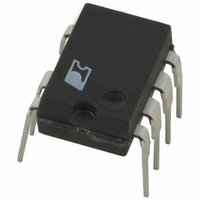
Package / Case
8-DIP (0.300", 7.62mm), 7 Leads
Output Voltage
5.6 V
Input / Supply Voltage (max)
265 VAC
Input / Supply Voltage (min)
85 VAC
Duty Cycle (max)
80 %
Switching Frequency
42 KHz
Supply Current
1.06 mA
Operating Temperature Range
- 40 C to + 150 C
Mounting Style
Through Hole
For Use With
596-1001 - KIT DESIGN ACCELERATOR ADAPTER
Lead Free Status / RoHS Status
Lead free / RoHS Compliant
Other names
596-1029-5
Available stocks
Company
Part Number
Manufacturer
Quantity
Price

Part Number:
LNK500PN
Manufacturer:
POWER
Quantity:
20 000


DRAIN Voltage .................................. ................ -0.3 V to 700 V
DRAIN Peak Current......................................400 mA
CONTROL Voltage ................................................ -0.3 V to 9 V
CONTROL Current (not to exceed 9 V)............100 mA
Storage Temperature .......................................... -65 °C to 150 °C
Operating Junction Temperature
Lead Temperature
Thermal Impedance: P or G Package:
Switching
Frequency
Low Switching
Frequency
Duty Cycle at Low
Switching
Frequency
Low Frequency
Duty Cycle Range
Maximum Duty
Cycle
PWM Gain
CONTROL Pin
Current at 30%
Duty Cycle
CONTROL Pin
Voltage
Dynamic
Impedance
CONTROL FUNCTIONS
Parameter
(θ
(θ
(3)
JA
JC
........................................................260 °C
) ........................... 70 °C/W
)
(1)
............................................... 11 °C/W
Symbol
DC
f
V
OSC(LOW)
DC
DC
DC
f
C(IDCT)
(2)
I
(RANGE)
Z
OSC
DCT
MAX
REG
C
..................... -40 °C to 150 °C
LF
ABSOLUTE MAXIMUM RATINGS
SOURCE = 0 V; T
Frequency Switching from f
Frequency = f
(Unless Otherwise Specified)
THERMAL IMPEDANCE
(2)
; 55 °C/W
f
I
I
Duty Cycle = DC
I
C
OSC(LOW)
C
C
= I
= I
Conditions
See Figure 12
= I
See Figure 4
I
T
T
C
DCT
DCT
DCT
J
J
I
= 1.5 mA
C
= 25 °C
= 25 °C
, T
OSC(LOW)
, T
, T
, T
= I
(3)
J
J
J
J
J
DCT
= 25 °C
= 25 °C
= 25 °C
= 25 °C
= -40 to 125 °C
Notes:
1. All voltages referenced to SOURCE, T
2. Normally limited by internal circuitry.
3. 1/16 in. from case for 5 seconds.
4. Maximum ratings specified may be applied, one at a time,
Notes:
1. Measured on pin 2 (SOURCE) close to plastic interface.
2. Soldered to 0.36 sq. in. (232 mm
3. Soldered to 1 sq. in. (645 mm
, T
without causing permanent damage to the product.
Exposure to Absolute Maximum Rating conditions for
extended periods of time may affect product reliability.
J
LF
= 25 °C
OSC
to
(1,4)
-0.45
Min
34.5
2.21
2.4
1.8
5.5
24
74
60
2
), 2 oz. (610 g/m
-0.35
Typ
3.15
2.30
5.75
2
3.8
), 2 oz. (610 g/m
42
30
77
90
A
= 25 °C.
Max
-0.25
49.5
2.39
120
LNK500
5.2
4.5
36
80
6
2
2
) copper clad.
) copper clad.
2/05
Units
D
%/µA
kHz
kHz
mA
%
%
%
Ω
V
11
Related parts for LNK500PN
Image
Part Number
Description
Manufacturer
Datasheet
Request
R

Part Number:
Description:
Energy Ef?cient, Cv Or Cv/cc Switcher For Very Low Cost Adapters And Chargers
Manufacturer:
Power Integrations, Inc.
Datasheet:

Part Number:
Description:
SOP-16
Manufacturer:
Power Integrations
Datasheet:
Part Number:
Description:
DIP8
Manufacturer:
Power Integrations
Datasheet:
Part Number:
Description:
TO-263
Manufacturer:
Power Integrations
Datasheet:
Part Number:
Description:
TO-263
Manufacturer:
Power Integrations
Datasheet: