LNK500PN Power Integrations, LNK500PN Datasheet - Page 13
LNK500PN
Manufacturer Part Number
LNK500PN
Description
IC SWIT OCP CV/CC HV 8DIP
Manufacturer
Power Integrations
Series
LinkSwitch®r
Datasheet
1.LNK500PN.pdf
(20 pages)
Specifications of LNK500PN
Output Isolation
Isolated
Frequency Range
24 ~ 49.5kHz
Voltage - Output
700V
Power (watts)
4W
Operating Temperature
-40°C ~ 150°C
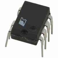
Package / Case
8-DIP (0.300", 7.62mm), 7 Leads
Output Voltage
5.6 V
Input / Supply Voltage (max)
265 VAC
Input / Supply Voltage (min)
85 VAC
Duty Cycle (max)
80 %
Switching Frequency
42 KHz
Supply Current
1.06 mA
Operating Temperature Range
- 40 C to + 150 C
Mounting Style
Through Hole
For Use With
596-1001 - KIT DESIGN ACCELERATOR ADAPTER
Lead Free Status / RoHS Status
Lead free / RoHS Compliant
Other names
596-1029-5
Available stocks
Company
Part Number
Manufacturer
Quantity
Price

Part Number:
LNK500PN
Manufacturer:
POWER
Quantity:
20 000


NOTES:
A. For specifications with negative values, a negative temperature coefficient corresponds to an increase in magnitude with
B. Breakdown voltage may be checked against minimum BV
C. I
D. This parameter is normalized to I
E. It is possible to start up and operate LinkSwitch at DRAIN voltages well below 36 V. However, the CONTROL pin charging
ON-State
Resistance
OFF-State Drain
Leakage Current
Breakdown Voltage
DRAIN Supply
Voltage
OUTPUT
increasing temperature, and a positive temperature coefficient corresponds to a decrease in magnitude with increasing
temperature.
exceeding minimum BV
through duty cycle control.
current is reduced, which affects start-up time, auto-restart frequency, and auto-restart duty cycle. Refer to the characteristic
graph on CONTROL pin charge current (I
C
is increased gradually to obtain maximum current limit at di/dt of 90 mA/µs. Increasing I
Parameter
DSS
Symbol
.
R
BV
I
DS(ON)
DSS
DSS
DCT
to correlate to power supply output current (it is multiplied by I
SOURCE = 0 V; T
C
I
) vs. DRAIN voltage (Figure 13) for low voltage operation characteristics.
(Unless Otherwise Specified)
D
= 25 mA
V
V
D
C
= 560 V, T
= 6.2 V, T
Conditions
See Figure 12
See Note B
See Note E
V
C
= 6.2 V
DSS
J
A
A
specification by ramping the DRAIN pin voltage up to but not
= -40 to 125 °C
= 125 °C
= 25 °C
T
T
J
J
= 100 °C
= 25 °C
Min
700
36
C
further would terminate the cycle
Typ
28
42
50
DCT
(nominal)/I
Max
LNK500
32
48
50
DCT
).
2/05
Units
D
µA
Ω
V
V
13
Related parts for LNK500PN
Image
Part Number
Description
Manufacturer
Datasheet
Request
R

Part Number:
Description:
Energy Ef?cient, Cv Or Cv/cc Switcher For Very Low Cost Adapters And Chargers
Manufacturer:
Power Integrations, Inc.
Datasheet:

Part Number:
Description:
SOP-16
Manufacturer:
Power Integrations
Datasheet:
Part Number:
Description:
DIP8
Manufacturer:
Power Integrations
Datasheet:
Part Number:
Description:
TO-263
Manufacturer:
Power Integrations
Datasheet:
Part Number:
Description:
TO-263
Manufacturer:
Power Integrations
Datasheet: