TOP258PN Power Integrations, TOP258PN Datasheet - Page 44
TOP258PN
Manufacturer Part Number
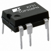
TOP258PN
Description
IC OFFLINE SWIT PROG OVP 8DIP
Manufacturer
Power Integrations
Series
TOPSwitch®-HXr
Type
Off Line Switcherr
Datasheet
1.TOP252GN-TL.pdf
(48 pages)
Specifications of TOP258PN
Output Isolation
Isolated
Frequency Range
119 ~ 145kHz
Voltage - Output
700V
Power (watts)
77W
Operating Temperature
-40°C ~ 150°C
Package / Case
8-DIP (0.300", 7.62mm), 7 Leads
Output Voltage
700 V
Input / Supply Voltage (max)
9 V
Input / Supply Voltage (min)
- 0.3 V
Duty Cycle (max)
78 %
Switching Frequency
132 KHz
Operating Temperature Range
- 40 C to + 150 C
Mounting Style
SMD/SMT
Maximum Operating Temperature
+ 150 C
Minimum Operating Temperature
- 40 C
Output Current
6.88 A
Output Power
48 W
For Use With
596-1193 - KIT REF DESIGN TOP HX FOR TOP258
Lead Free Status / RoHS Status
Lead free / RoHS Compliant
Other names
596-1189-5
Available stocks
Company
Part Number
Manufacturer
Quantity
Price
Company:

Part Number:
TOP258PN
Manufacturer:
PowerInt
Quantity:
2 100
Company:
Part Number:
TOP258PN
Manufacturer:
PANASONIC
Quantity:
230
Part Number:
TOP258PN
Manufacturer:
CN/如韵
Quantity:
20 000


Rev. F 01/09
SEATING
PLANE
44
.200 (5.08) Max
-T-
.100 (2.54) BSC
.070 (1.78) BSC
.125 (3.18)
.145 (3.68)
.240 (6.10)
.260 (6.60)
.020 (.51) Min
SEATING
PLANE
-E-
Pin 1
-D-
TOP252-262
.040 (1.02)
.030 (.76)
10
1
.014 (.36)
.022 (.56)
⊕
D S .004 (.10)
.367 (9.32)
.387 (9.83)
.367 (9.32)
.387 (9.83)
.048 (1.22)
.053 (1.35)
⊕
T E D S .010 (.25) M
6
5
.014 (.36)
.022 (.56)
.125 (3.18)
.145 (3.68)
.057 (1.45)
.068 (1.73)
.240 (6.10)
.260 (6.60)
.120 (3.05)
.140 (3.56)
.137 (3.48)
.120 (3.05)
.140 (3.56)
MINIMUM
MINIMUM
(NOTE 6)
.015 (.38)
-D-
-E-
⊕
.010 (.25) M
-F-
SDIP-10C
DIP-8C
F D E
Notes:
1. Package dimensions conform to JEDEC specification
2. Controlling dimensions are inches. Millimeter sizes are
3. Dimensions shown do not include mold flash or other
4. Pin locations start with Pin 1, and continue counter-clock-
5. Minimum metal to metal spacing at the package body for
6. Lead width measured at package body.
7. Lead spacing measured with the leads constrained to be
Notes:
1. Package dimensions conform to JEDEC specification
2. Controlling dimensions are inches. Millimeter sizes are
3. Dimensions shown do not include mold flash or other
4. D, E and F are reference datums.
5. Dimensioning and tolerancing conform to ASME Y14.5M-1994.
MS-001-AB (Issue B 7/85) for standard dual-in-line (DIP)
package with .300 inch row spacing.
shown in parentheses.
protrusions. Mold flash or protrusions shall not exceed
.006 (.15) on any side.
wise to Pin 8 when viewed from the top. The notch and/or
dimple are aids in locating Pin 1. Pin 3 is omitted.
the omitted lead location is .137 inch (3.48 mm).
perpendicular to plane T.
MS-019.
shown in parentheses.
protrusions. Mold flash or protrusions shall not exceed
.006 (.15) on any side.
.008 (.20)
.015 (.38)
.300 (7.62) BSC
.300 (7.62)
.390 (9.91)
(NOTE 7)
.008 (.20)
.015 (.38)
.300 (7.62)
.340 (8.64
.300 (7.62)
.390 (9.91)
.300 BSC
www.powerint.com
PI-3933-100504
PI-4648-041107
P08C
P10C
Related parts for TOP258PN
Image
Part Number
Description
Manufacturer
Datasheet
Request
R

Part Number:
Description:
SOP-16
Manufacturer:
Power Integrations
Datasheet:
Part Number:
Description:
DIP8
Manufacturer:
Power Integrations
Datasheet:
Part Number:
Description:
TO-263
Manufacturer:
Power Integrations
Datasheet:
Part Number:
Description:
TO-263
Manufacturer:
Power Integrations
Datasheet:
Part Number:
Description:
Manufacturer:
Power Integrations
Datasheet: