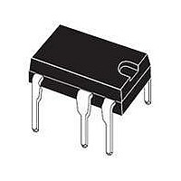
VIPER25HN STMicroelectronics, VIPER25HN Datasheet - Page 25

VIPER25HN
Manufacturer Part Number
VIPER25HN
Description
IC OFFLINE CONV PWM OVP 7DIP
Manufacturer
STMicroelectronics
Series
VIPer™ plusr
Datasheet
1.VIPER25LN.pdf
(40 pages)
Specifications of VIPER25HN
Output Isolation
Isolated
Frequency Range
200 ~ 250kHz
Voltage - Input
8.5 ~ 23.5 V
Voltage - Output
800V
Power (watts)
24W
Operating Temperature
-40°C ~ 150°C
Package / Case
8-DIP (0.300", 7.62mm), 7 Leads
Input Voltage
8.5 V to 23.5 V
Switching Frequency
225 KHz
Mounting Style
Through Hole
Lead Free Status / RoHS Status
Lead free / RoHS Compliant
Other names
497-9073-5
Available stocks
Company
Part Number
Manufacturer
Quantity
Price
Company:
Part Number:
VIPER25HN
Manufacturer:
KIONIX
Quantity:
4 460
Part Number:
VIPER25HN
Manufacturer:
ST
Quantity:
20 000
VIPER25
Figure 31. Typical power capability vs input voltage in quasi-resonant converter’s
In order to proper select the value of the resistance R
are known the proper I
voltage. The following approximated formula calculates the value of the resistor R
Equation 3
Where:
●
●
●
The
Equation 4
Where:
V
respectively (see
ZCD1
R
V
n
I
the selected I
current is reported on
ZCD1
aux
LIM
in_Max
and V
Value can be calculated from the following formula knowing the R
is the primary to auxiliary winding turn ratio
, and I
and V
ZCD2
R
ZCD2
LIM
Figure 15 on page 12
are the ZCD pin voltages when the sunk current is I
Dlim
in_min
=
are the currents needed to sink from the ZCD pin, in order to obtain
Max
set points, respectively at V
Dlim
are the maximum and minimum converter rectified input voltage
2.5
1.5
0.5
2
1
1
⎛
⎜
⎜
⎜
⎜
⎜
⎜
⎜ ⎜
⎝
set points at minimum and at the maximum converter input
Figure 16 on page 12
I
ZCD
Doc ID 15585 Rev 4
1
R
−
1.5
FF
V
V
n
in
=
ZCD
aux
_
min
).
n
R
V
aux
1
2
FF
in
+
_
⋅
V
max
I (
ZCD
V
ZCD
V
inmin
2.5
in
−
).
system optimally
1
1
in_max
compensated
compensated
V
,
system not
−
I
in
ZCD
I
_
ZCD
FF
min
2
3
(see
2
and V
−
)
V
V
in
n
Figure 32 on page 26
ZCD
_
aux
in_min
3.5
max
R
2
FF
+
, the graph I
Operation description
V
ZCD1
ZCD
4
2
FF
and I
⎞
⎟
⎟
⎟
⎟
⎟
⎟
⎟ ⎟
⎠
value:
Dlim
ZCD2
FF
), once
vs I
25/40
ZCD


