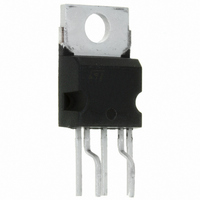
VIPER100-E STMicroelectronics, VIPER100-E Datasheet - Page 14

VIPER100-E
Manufacturer Part Number
VIPER100-E
Description
IC SWIT PWM SMPS CM PENTAWATT5
Manufacturer
STMicroelectronics
Series
VIPER™r
Datasheet
1.VIPER100-E.pdf
(29 pages)
Specifications of VIPER100-E
Output Isolation
Isolated
Frequency Range
90 ~ 200kHz
Voltage - Input
8 ~ 15 V
Voltage - Output
620V
Power (watts)
82W
Operating Temperature
25°C ~ 125°C
Package / Case
Pentawatt-5 HV (Bent and Staggered Leads)
Output Voltage
620 V
Output Current
3 A
Input Voltage
0 V to 15 V
Switching Frequency
200 KHz
Operating Temperature Range
- 65 C to + 150 C
Mounting Style
Through Hole
No. Of Pins
5
Ic Generic Number
100
Output Current Max
5.3A
Frequency
200kHz
Leaded Process Compatible
Yes
Output Current Min
3A
Rohs Compliant
Yes
Lead Free Status / RoHS Status
Lead free / RoHS Compliant
Other names
497-6161-5
Available stocks
Company
Part Number
Manufacturer
Quantity
Price
Company:
Part Number:
VIPER100-E
Manufacturer:
ROHM
Quantity:
12 000
Company:
Part Number:
VIPER100-E
Manufacturer:
STMicroelectronics
Quantity:
1 818
5 Operation Description
5.5
5.6
5.7
14/29
External Clock Synchronization:
The OSC pin provides a synchronisation capability when connected to an external frequency
source.
If the proposed schematic is used, the pulse duration must be kept at a low value (500ns is
sufficient) for minimizing consumption. The optocoupler must be able to provide 20mA through
the optotransistor.
Primary Peak Current Limitation
The primary I
simple circuit shown in
the COMP pin in order to limit the primary peak current of the device to a value:
where:
The suggested value for R
Over-Temperature Protection
Over-temperature protection is based on chip temperature sensing. The minimum junction
temperature at which over-temperature cut-out occurs is 140ºC, while the typical value is
170ºC. The device is automatically restarted when the junction temperature decreases to the
restart temperature threshold that is typically 40ºC below the shutdown value
I
V
D PEAK
COMP
Figure 21
=
=
DPEAK
0.6
V
------------------------------- -
COMP
×
shows one possible schematic to be adapted, depending the specific needs.
R
------------------ -
H
1
ID
current and, consequently, the output power can be limited using the
R
+
–
2
R
0.5
Figure 22
2
1
+R
2
is in the range of 220KΩ.
. The circuit based on Q1, R
1
and R
2
clamps the voltage on
(see Figure 13)
VIPer100-E


