TNY266PN Power Integrations, TNY266PN Datasheet - Page 6
TNY266PN
Manufacturer Part Number
TNY266PN
Description
IC OFFLINE SWIT OTP OCP HV 8DIP
Manufacturer
Power Integrations
Series
TinySwitch®-IIr
Specifications of TNY266PN
Output Isolation
Isolated
Frequency Range
124 ~ 140kHz
Voltage - Output
700V
Power (watts)
15W
Operating Temperature
-40°C ~ 150°C
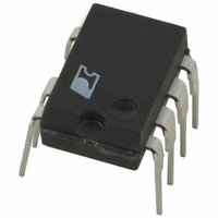
Package / Case
8-DIP (0.300", 7.62mm), 7 Leads
Output Voltage
5.8 V
Input / Supply Voltage (max)
265 VAC
Input / Supply Voltage (min)
85 VAC
Duty Cycle (max)
68 %
Switching Frequency
132 KHz
Supply Current
265 uA
Operating Temperature Range
- 40 C to + 150 C
Mounting Style
Through Hole
Supply Voltage
265VAC
Digital Ic Case Style
DIP
No. Of Pins
8
No. Of Regulated Outputs
1
Filter Terminals
DIP
Rohs Compliant
Yes
On Resistance Rds(on)
14ohm
Lead Free Status / RoHS Status
Lead free / RoHS Compliant
Other names
596-1051-5
Available stocks
Company
Part Number
Manufacturer
Quantity
Price
Company:

Part Number:
TNY266PN
Manufacturer:
PHILIPS
Quantity:
3 000
Company:
Part Number:
TNY266PN
Manufacturer:
PowerInt
Quantity:
84 450
Part Number:
TNY266PN
Manufacturer:
POWER
Quantity:
20 000


two main benefi ts. First, for a nominal application, this
eliminates the cost of a bias winding and associated
components. Secondly, for battery charger applications, the
current-voltage characteristic often allows the output voltage
to fall close to zero volts while still delivering power. This type
of application normally requires a forward-bias winding which
has many more associated components. With TinySwitch-II,
neither are necessary. For applications that require a very low
no-load power consumption (50 mW), a resistor from a bias
winding to the BYPASS pin can provide the power to the chip.
The minimum recommended current supplied is 750 μA. The
BYPASS pin in this case will be clamped at 6.3 V. This method
will eliminate the power draw from the DRAIN pin, thereby
200
100
Rev. H 02/09
Figure 9.
400
200
Figure 10. TinySwitch-II Power-up with Optional External UV
10
0
5
0
0
6
V
0
I
CLOCK
D
DRAIN
DRAIN
MAX
V
V
EN
V
TinySwitch-II Operation at Very Light Load.
V
DC-INPUT
Resistor (2 MΩ) Connected to EN/UV Pin.
DRAIN
BYPASS
TNY263-268
Time (ms)
1
PI-2661-072400
2
200
100
200
100
Figure 11. TinySwitch-II Power-up without Optional External UV
200
100
Figure 13. Slow Power-down Timing with Optional External
400
200
400
300
200
100
400
300
200
100
10
Figure 12. Normal Power-down Timing (without UV).
0
5
0
0
0
0
0
0
0
0
0
V
Resistor Connected to EN/UV Pin.
V
(2 MΩ) UV Resistor Connected to EN/UV Pin.
V
DC-INPUT
DRAIN
BYPASS
Time (ms)
Time (s)
Time (s)
2.5
.5
1
V
V
V
DC-INPUT
DC-INPUT
V
DRAIN
DRAIN
www.powerint.com
2
5
1
Related parts for TNY266PN
Image
Part Number
Description
Manufacturer
Datasheet
Request
R

Part Number:
Description:
Manufacturer:
Power Integrations, Inc.
Datasheet:

Part Number:
Description:
SOP-16
Manufacturer:
Power Integrations
Datasheet:
Part Number:
Description:
DIP8
Manufacturer:
Power Integrations
Datasheet:
Part Number:
Description:
TO-263
Manufacturer:
Power Integrations
Datasheet:
Part Number:
Description:
TO-263
Manufacturer:
Power Integrations
Datasheet: