TOP242Y Power Integrations, TOP242Y Datasheet - Page 48
TOP242Y
Manufacturer Part Number
TOP242Y
Description
IC OFFLINE SWIT UVLO HV TO220
Manufacturer
Power Integrations
Series
TOPSwitch®-GXr
Datasheet
1.TOP242GN-TL.pdf
(52 pages)
Specifications of TOP242Y
Output Isolation
Isolated
Frequency Range
66 ~ 132kHz
Voltage - Output
700V
Power (watts)
22W
Operating Temperature
-40°C ~ 150°C
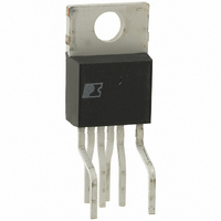
Package / Case
TO-220-7 (Formed Leads), 5 Leads
Lead Free Status / RoHS Status
Contains lead / RoHS non-compliant
Available stocks
Company
Part Number
Manufacturer
Quantity
Price
Company:

Part Number:
TOP242Y
Manufacturer:
POWER
Quantity:
12 500
Company:
Part Number:
TOP242YN
Manufacturer:
ATMEL
Quantity:
2 400
Part Number:
TOP242YN
Manufacturer:
POWER
Quantity:
20 000


48
.260 (6.60)
.240 (6.10)
.100 (2.54) BSC
.125 (3.18)
.145 (3.68)
TOP242-250
-T-
.032 (.81)
.037 (.94)
Pin 1
.125 (3.18)
.145 (3.68)
-E-
.240 (6.10)
.260 (6.60)
-D-
SEATING
PLANE
O
11/05
-E-
Pin 1
-D-
.014 (.36)
.022 (.56)
⊕
.367 (9.32)
.387 (9.83)
⊕
D S .004 (.10)
D S .004 (.10)
.100 (2.54) (BSC)
.367 (9.32)
.387 (9.83)
.048 (1.22)
.053 (1.35)
⊕
T E D S .010 (.25) M
.048 (1.22)
.053 (1.35)
.137 (3.48)
.009 (.23)
MINIMUM
.137 (3.48)
⊕
MINIMUM
.372 (9.45)
.388 (9.86)
E S
.057 (1.45)
.068 (1.73)
.120 (3.05)
.140 (3.56)
.057 (1.45)
.068 (1.73)
MINIMUM
(NOTE 6)
.015 (.38)
(NOTE 5)
.010 (.25)
SMD-8B
DIP-8B
.004 (.10)
.012 (.30)
Notes:
1. Package dimensions conform to JEDEC specification
2. Controlling dimensions are inches. Millimeter sizes are
3. Dimensions shown do not include mold flash or other
4. Pin locations start with Pin 1, and continue counter-clock-
5. Minimum metal to metal spacing at the package body for
6. Lead width measured at package body.
7. Lead spacing measured with the leads constrained to be
Pin 1
MS-001-AB (Issue B 7/85) for standard dual-in-line (DIP)
package with .300 inch row spacing.
shown in parentheses.
protrusions. Mold flash or protrusions shall not exceed
.006 (.15) on any side.
wise to Pin 8 when viewed from the top. The notch and/or
dimple are aids in locating Pin 1. Pin 6 is omitted.
the omitted lead location is .137 inch (3.48 mm).
perpendicular to plane T.
Solder Pad Dimensions
.004 (.10)
.046 .060
.008 (.20)
.015 (.38)
.086
.300 (7.62) BSC
.186
.036 (0.91)
.044 (1.12)
.300 (7.62)
.390 (9.91)
(NOTE 7)
.286
.060 .046
.080
.420
0 -
°
8
Notes:
1. Controlling dimensions are
2. Dimensions shown do not
3. Pin locations start with Pin 1,
4. Minimum metal to metal
5. Lead width measured at
6. D and E are referenced
°
inches. Millimeter sizes are
shown in parentheses.
include mold flash or other
protrusions. Mold flash or
protrusions shall not exceed
.006 (.15) on any side.
and continue counter-clock-
wise to Pin 8 when viewed
from the top. Pin 6 is omitted.
spacing at the package body
for the omitted lead location
is .137 inch (3.48 mm).
package body.
datums on the package
body.
PI-2551-121504
PI-2546-121504
G08B
P08B
Related parts for TOP242Y
Image
Part Number
Description
Manufacturer
Datasheet
Request
R

Part Number:
Description:
IC OFFLINE CTRLR SMPS CM TO220
Manufacturer:
Infineon Technologies
Datasheet:

Part Number:
Description:
IC OFFLINE CTRLR SMPS CM TO220
Manufacturer:
Infineon Technologies
Datasheet:

Part Number:
Description:
SOP-16
Manufacturer:
Power Integrations
Datasheet:
Part Number:
Description:
DIP8
Manufacturer:
Power Integrations
Datasheet:
Part Number:
Description:
TO-263
Manufacturer:
Power Integrations
Datasheet: