VIPER100A STMicroelectronics, VIPER100A Datasheet
VIPER100A
Specifications of VIPER100A
Available stocks


Related parts for VIPER100A


VIPER100A Summary of contents
Page 1
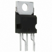
... OSC ON/OFF OSCILLATOR SECURITY PWM LATCH LATCH S FF UVLO R LOGIC OVERTEMP. DETECTOR 1.7 μ 250 ns _ DELAY BLANKING 4.5 V COMP VIPer100/SP VIPer100A/ASP SMPS PRIMARY I.C. Package PENTAWATT HV (022Y) DRAIN 0. V/A _ CURRENT AMPLIFIER SOURCE www.st.com Rev 2 1/24 24 ...
Page 2
... Current and Voltage Convention V 2/24 Parameter =25ºC c Parameter PENTAWATT VDD DRAIN I - OSC OSC + 13V COMP SOURCE DD I COMP V OSC V COMP VIPer100/SP - VIPer100A/ASP Value –0.3 to 620 –0.3 to 700 Internally limited ±2 4000 2 1.4 82 Internally limited -65 to 150 PENTAWATT HV Max 1.4 Max 60 PENTAWATT HV (022Y ...
Page 3
... VIPer100/SP - VIPer100A/ASP Table 5. Ordering Numbers PENTAWATT HV VIPer100 VIPer100A Pins Functional Description Drain Pin (Integrated Power MOSFET Drain): Integrated Power MOSFET drain pin. It provides internal bias current during start-up via an integrated high voltage current source which is switched off during normal operation. The device is able to handle an unclamped current during its normal operation, assuring self protection against voltage surges, PCB stray inductance, and allowing a snubberless operation for low output power ...
Page 4
... Table 6. Avalance Characteristics Symbol Avalanche Current, Repetitive or Not Repetitive (pulse width limited by TJ max; δ < 1%) I D(AR) for VIPer100/SP (see Figure 15) for VIPer100A/ASP (*) (see Figure 15) Single Pulse Avalanche Energy E (AR) (starting TJ = 25ºC, I Electrical Chracteristics (TJ = 25°C; V Table 7. Power Section Symbol ...
Page 5
... VIPer100/SP - VIPer100A/ASP Table 8. Supply Section Symbol Parameter I Start-Up Charging Current DDch I Operating Supply Current DD0 I DD1 Operating Supply Current V Undervoltage Shutdown DDoff V Undervoltage Reset DDon V Hysteresis Start-up DDhyst Table 9. Oscillator Section Symbol Parameter Oscillator Frequency Total F SW Variation V Oscillator Peak Voltage ...
Page 6
... Shutdown and Overtemperature Section Symbol Parameter V Restart Threshold COMPth t Disable Set Up Time DISsu Thermal Shutdown T tsd Temperature T Thermal Shutdown Hysteresis (see Figure 7) hyst 6/24 VIPer100/SP - VIPer100A/ASP Test Conditions‘ COMP I = 10mA DPEAK V = 12V; COMP pin open Test Conditions‘ (see Figure 7) (see Figure 7) ...
Page 7
... VIPer100/SP - VIPer100A/ASP Figure 4. V Regulation Point Slope = A/V COM COM PLO V DDreg Figure 6. Transition Time I D 10% Ipeak Figure 8. Breakdown Voltage vs. Temperature Figure 9. 1.15 BV DSS (Normalized) 1.1 1. Temperature (°C) Figure FC00150 Figure FC00160 FC00180 (%) 80 100 120 Undervoltage Lockout ...
Page 8
... Figure 10. Start-Up Waveforms Figure 11. Over-temperature Protection T tsd 8/ yst off VIPer100/SP - VIPer100A/ASP SC101 91 ...
Page 9
... VIPer100/SP - VIPer100A/ASP Figure 12. Oscillator VDD Rt OSC 22nF 15nF 1,000 Ct = 1.5 nF 500 300 Ct = 4.7 nF 200 100 CLK FC00050 Forbidden area Ct(nF) = Forbidden area 40kHz Oscillator frequency vs Rt and 2 (kΩ) >1.2K Ω For R t and ≥ 15nF if F ≤ 40KHz 2.3 ⎛ ...
Page 10
... RCOMP = 27k RCOMP = 12k 20 0 (20) 0.001 Figure 14. Error Amplifier Phase Response 200 150 100 50 0 (50) 0.001 10/24 0.01 0 Frequency (kHz) 0.01 0 Frequency (kHz) VIPer100/SP - VIPer100A/ASP FC00200 100 1,000 FC00210 RCOMP = +∞ RCOMP = 270k RCOMP = 82k RCOMP = 27k RCOMP = 12k 100 1,000 ...
Page 11
... VIPer100/SP - VIPer100A/ASP Figure 15. Avalanche Test Circuit 1 OSC 13V C1 U1 BT2 VIPer100 47uF 12V 16V 1mH 2 3 VDD DRAIN - + COMP SOURCE 100 STHV102FI in parallel R1 47 GENERATOR INPUT 500us PULSE FC00195 BT1 0 to 20V 11/24 ...
Page 12
... Figure 17. Offline Power Supply With Optocoupler Feedback F1 TR2 12/24 BR1 VDD DRAIN - OSC VIPer100 + 13V COMP SOURCE C6 C11 R3 BR1 TR1 VDD DRAIN - U1 OSC VIPer100 + 13V COMP SOURCE C6 C11 R3 VIPer100/SP - VIPer100A/ASP TR1 C10 U1 FC00081 D2 L2 +Vcc C7 C9 GND C10 R6 ISO1 FC00091 +Vcc GND ...
Page 13
... VIPer100/SP - VIPer100A/ASP Operation Description: Current Mode Topology: The current mode control method, like the one integrated in the VIPer100/100A, uses two control loops - an inner current control loop and an outer loop for voltage control. When the Power MOSFET output transistor is on, the inductor current (primary side of the transformer) is monitored with a SenseFET technique and converted into a voltage V amplified output voltage error) the power switch is switched off ...
Page 14
... UVLO logic, and the device goes back to the inactive DDoff pin must be sized according to the time needed by the converter DD depends on many parameters, among which SS pin when switching. Refer to specified I DD and V DDon VIPer100/SP - VIPer100A/ASP pin. As soon DD of the UVLO logic, the device > C -------------------- ...
Page 15
... VIPer100/SP - VIPer100A/ASP Figure 18. Behaviour of the high voltage current source at start-up VDD VDDon VDDoff VDD VDD Ref. UNDERVOLTAGE Auxiliary primary LOCK OUT LOGIC winding VIPer100 Start up duty cycle ~ 12 DRAIN SOURCE FC00100 15/24 ...
Page 16
... ∂ ∂ can be related to G VOL and therefore A COMP is in the range of 220KΩ. 2 VIPer100/SP - VIPer100A/ASP and COMP are subject to large tolerances. An VOL and R clamps the voltage on the COMP – 0 --- -- --- - -- - --- -- --- - -- - - - ...
Page 17
... VIPer100/SP - VIPer100A/ASP Over-Temperature Protection Over-temperature protection is based on chip temperature sensing. The minimum junction temperature at which over-temperature cut-out occurs is 140ºC, while the typical value is 170ºC. The device is automatically restarted when the junction temperature decreases to the restart temperature threshold that is typically 40ºC below the shutdown value (see Figure 11) page 8.. ...
Page 18
... V The simple RC filter shown in (see Figure 25) page 17 can be implemented to improve the application immunity to such surges. 18/24 R1 (Optional) R2 39R VDD DRAIN - OSC + 13V COMP SOURCE VIPerXX0 VIPer100/SP - VIPer100A/ASP D1 Auxilliary winding internal DD bulk capacitor. DD ...
Page 19
... VIPer100/SP - VIPer100A/ASP Figure 26. Recommended Layout R1 C1 From input diodes bridge C2 Layout Considerations Some simple rules insure a correct running of switching power supplies. They may be classified into two categories: - Minimizing power loops: The switched power current must be carefully analysed and the corresponding paths must be as small an inner loop area as possible. This avoids radiated EMC noises, conducted EMC noises by magnetic coupling, and provides a better efficiency by eliminating parasitic inductances, especially on secondary side ...
Page 20
... VIPer100/SP - VIPer100A/ASP inch Min. Typ. Max. 0.169 0.189 0.046 0.054 0.094 0.11 0.014 0.022 0.024 0.031 0.193 0.205 0.295 0.307 0.366 0.382 ...
Page 21
... VIPer100/SP - VIPer100A/ASP Pentawatt HV 022Y ( Vertical High Pitch ) Mechanical Data Dim Min. A 4.30 C 1.17 D 2.40 E 0.35 F 0.60 G1 4.91 G2 7. 10.05 L 16.42 L1 14.60 L3 20.52 L5 2.60 L6 15.10 L7 6.00 M 2. Diam 3.65 mm. Typ. Maw. 4.80 1.37 2.80 0.55 0.80 5.21 7.80 9.70 10.40 10 ...
Page 22
... Figure 27. Pentawatt HV Tube Shipment ( no suffix ) 22/24 VIPer100/SP - VIPer100A/ASP Base Q.ty 50 1000 Bulk Q.ty Tube length ( ± 0.5 ) 532 33 ± 0 All dimensions are in mm. ...
Page 23
... VIPer100/SP - VIPer100A/ASP Table 13. Revision history Date Revision 02-May-2005 08-JUn-2005 1 Initial release. 2 Update without PowerSO-10 Changes TM 23/24 ...
Page 24
... Australia - Belgium - Brazil - Canada - China - Czech Republic - Finland - France - Germany - Hong Kong - India - Israel - Italy - Japan - Malaysia - Malta - Morocco - Singapore - Spain - Sweden - Switzerland - United Kingdom - United States of America 24/24 © 2005 STMicroelectronics - All rights reserved STMicroelectronics group of companies www.st.com VIPer100/SP - VIPer100A/ASP ...