VIPER50SP STMicroelectronics, VIPER50SP Datasheet
VIPER50SP
Specifications of VIPER50SP
Available stocks


Related parts for VIPER50SP


VIPER50SP Summary of contents
Page 1
TYPE V DSS VIPer50/SP 620V 1.5 A VIPer50A/ASP 700V 1.5 A ADJUSTABLE SWITCHING FREQUENCY UP TO 200 kHz CURRENT MODE CONTROL SOFT START AND SHUT DOWN CONTROL AUTOMATIC BURST MODE OPERATION IN STAND-BY CONDITION ABLE TO MEET “BLUE ANGEL” ...
Page 2
ABSOLUTE MAXIMUM RATING Symbol Continuous Drain-Source Voltage (T V for VIPer50/SP DS for VIPer50A/ASP I Maximum Current D V Supply Voltage DD V Voltage Range Input OSC V Voltage Range Input COMP I Maximum Continuous Current COMP V Electrostatic Discharge ...
Page 3
... Note that despite at 13V. For DD the connection of R frequency change occurs for V pin by transformer to 15V. It also provides a synchronization capability, when connected to an external frequency source. PowerSO-10™ VIPer50SP VIPer50ASP above, secondary regulation significant t DD varying from 8V DD ...
Page 4
AVALANCHE CHARACTERISTICS Symbol Avalanche Current, Repetitive or Not Repetitive (pulse widht limited D(AR) for VIPer50/SP for VIPer50A/ASP Single Pulse Avalanche Energy E (ar) (starting T =25º ELECTRICAL CHARACTERISTICS (T POWER SECTION Symbol Parameter ...
Page 5
VIPer50/SP - VIPer50A/ASP ELECTRICAL CHARACTERISTICS (continued) OSCILLATOR SECTION Symbol Parameter Oscillator Frequency F SW Total Variation V Oscillator Peak Voltage OSCih V Oscillator Valley Voltage OSCil ERROR AMPLIFIER SECTION Symbol Parameter V V Regulation Point DDreg DD V Total Variation ...
Page 6
Figure 1: V Regulation Point DD I COMP Slope = mA/V COMPHI 0 I COMPLO V DDreg Figure 3: Transition Time I D 10% Ipeak Figure 5: ...
Page 7
VIPer50/SP - VIPer50A/ASP Figure 7: Start-Up Waveforms Figure 8: Overtemperature Protection tsd hyst V ddon V ddoff V comp 7/ tsc SC10191 ...
Page 8
Figure 9: Oscillator VDD Rt OSC 22nF 15nF 1,000 500 300 200 100 50 30 For R and CLK FC00050 Forbidden area Ct(nF) = Forbidden area 40kHz Oscillator frequency vs Rt and Ct ...
Page 9
VIPer50/SP - VIPer50A/ASP Figure 10: Error Amplifier Frequency Response 60 RCOMP = + RCOMP = 270k 40 RCOMP = 82k RCOMP = 27k RCOMP = 12k 20 0 (20) 0.001 Figure 11: Error Amplifier Phase Response 200 150 100 50 ...
Page 10
Figure 12: Avalanche Test Circuit 2 VDD 1 OSC 13V C1 U1 BT2 VIPer100 47uF 12V 16V 1mH 3 DRAIN STHV102FI in parallel - + COMP SOURCE 100 VIPer50/SP - VIPer50A/ASP ...
Page 11
Figure 13: Off Line Power Supply With Auxiliary Supply Feedback F1 TR2 OSC C5 Figure 14: Off Line Power Supply With Optocoupler Feedback ...
Page 12
OPERATION DESCRIPTION: CURRENT MODE TOPOLOGY The current mode control method, like the one integrated in the VIPer50/50A uses two control loops - an inner current control loop and an outer loop for voltage control. When the Power MOSFET output transistor ...
Page 13
UVLO logic, the device turns into active mode and starts switching. The start up current generator is switched off, and the converter should normally provide the needed current on the V pin through the auxiliary DD winding of the transformer, ...
Page 14
TRANSCONDUCTANCE ERROR AMPLIFIER The VIPer50/50A includes a transconductance error amplifier. Transconductance Gm is the change in output current (I ) versus change in COMP input voltage (V ). Thus COMP ----------------------- - The ...
Page 15
COMP pin in order to limit the primary peak current of the device to a value: V – 0.5 COMP I DPEAK ------------------------------------- = H ID where --------------------- - V COMP 0 ...
Page 16
Figure 22: Input Voltage Surges Protection C2 C1 Bulk capacitor 22nF ELECTRICAL OVER STRESS RUGGEDNESS The VIPer may be submitted to electrical over stress caused by violent input voltage surges or lightning. Following the enclosed Considerations chapter rules is the ...
Page 17
Figure 23: Recommended Layout OSC A…‚€Ãvƒˆ‡ qv‚qr†Ãi…vqtr U1 VIPerXX0 C2 LAYOUT CONSIDERATIONS Some simple rules insure a correct running of switching power supplies. They may be classified into two categories minimize power loops: the way ...
Page 18
PowerSO-10™ MECHANICAL DATA DIM. MIN. A 3.35 A (*) 3.4 A1 0.00 B 0.40 B (*) 0.37 C 0.35 C (*) 0.23 D 9.40 D1 7.40 E 9.30 E2 7.20 E2 (*) 7.30 E4 5.90 E4 (*) 5. ...
Page 19
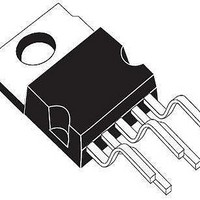
PENTAWATT HV MECHANICAL DATA mm. DIM. MIN. TYP A 4.30 C 1.17 D 2.40 E 0.35 F 0.60 G1 4.91 G2 7.49 9. 10. 15.60 L1 14.60 L2 21.20 L3 22.20 L5 2.60 L6 15.10 L7 ...
Page 20
PENTAWATT HV 022Y (VERTICAL HIGH PITCH) MECHANICAL DATA mm. DIM. MIN. TYP A 4.30 C 1.17 D 2.40 E 0.35 F 0.60 G1 4.91 G2 7. 10.05 L 16.42 L1 14.60 L3 20.52 L5 2.60 L6 ...
Page 21
SUGGESTED PAD LAYOUT PowerSO-10™ 14.6 - 14 TAPE AND REEL SHIPMENT (suffix “13TR”) TAPE DIMENSIONS According to Electronic Industries Association (EIA) Standard 481 rev. A, ...
Page 22
VIPer50/SP - VIPer50A/ASP PENTAWATT HV TUBE SHIPMENT (no suffix 22/23 Base Q.ty Bulk Q.ty Tube length (± 0. (± 0.1) C All dimensions are in mm. 50 1000 532 18 33 ...
Page 23
... STMicroelectronics. Specifications mentioned in this publication are subject to change without notice. This publication supersedes and replaces all information previously supplied. STMicroelectronics products are not authorized for use as critical components in life support devices or systems without express written approval of STMicroelectronics. 2003 STMicroelectronics - Printed in ITALY- All Rights Reserved. ...