P-130SCR/A34 Panasonic - BSG, P-130SCR/A34 Datasheet - Page 17
P-130SCR/A34
Manufacturer Part Number
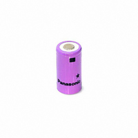
P-130SCR/A34
Description
BATTERY NICAD SC SIZE R TYPE
Manufacturer
Panasonic - BSG
Datasheet
1.P-130SCRF2.pdf
(87 pages)
Specifications of P-130SCR/A34
Battery Cell Size
SC - Flat Top
Voltage - Rated
1.2V
Capacity
1300mAh
Rechargeability
Yes
Termination Style
Flat Top (Non-Extending)
Internal Resistance
*
Standard Charge Time
*
Standard Charge Current
*
Weight
1.66 oz (47.06g)
Lead Free Status / RoHS Status
Lead free / RoHS compliant by exemption
Size / Dimension
-
Other names
P-130SCR
P-130SCR/FT
P159
P-130SCR/FT
P159


CHARGE METHODS FOR NI-CD BATTERIES - CONTINUED
(3) Precautions
•
•
•
•
•
•
•
•
This method is suitable for rapid charge Ni-Cd
batteries.
The charge current should be 0.5 CmA ~ 1 CmA.
If charged at less than 0.5 CmA, the voltage drop
after the peak voltage is reached might be too
small for the -
overcharge. The maximum charge current will
vary according to the specific type of battery, so it
is important to select the appropriate charge
current. (See (5) in Fig. 6)
A constant-current power supply circuit is
required. If fluctuations in the charge current
occur as a result of fluctuations in the power
supply voltage, the charge voltage will change,
and faulty operation (stopping of charge before
completion) of the charger might occur.
The voltage detector shown in the block diagram
must be provided with a noise canceller in order
to prevent external noise from causing faulty
operation (stopping of charge before completion)
of the charger.
An initial delay timer is needed in order to prevent
faulty operation (stopping of charge before
completion) of the charger from being caused by
any false -
charge.
False -
are left unused for a long period of time or
excessively discharged, the charge voltage (false
-
(1) in Fig 6)
Initial delay timer: Prevents the -
circuit from functioning for a certain length of time
after rapid charge is begun.
Be sure that the -
faulty operation (overcharge or insufficient
charge) of the charger might occur. (See (1) in
Fig. 6)
A voltage detection switch must be provided in
order to change from the rapid-charge current to
the trickle charge current when the charge voltage
reaches the predetermined level.
This predetermined level varies according to the
type of battery, so consult Panasonic for the
specific level. The trickle charge current should
be 0.05 CmA. (See (2) and (6) in Fig. 6)
If a voltage detection switch is provided in order to
switch the charger to the rapid charge mode, set
the voltage value to 0.8 to 1.0 V/cell. In addition, for
the period of initial charge (before the start of rapid
charge) until the battery voltage reaches the
∆
V) may swing at the beginning of charge. (See
∆
V phenomenon: When Ni-Cd batteries
∆
V phenomenon at the beginning of
∆
V cut-off to function, resulting in
∆
V value is correct. If it is not,
NICKEL CADMIUM HANDBOOK, PAGE 16
∆
V detection
•
•
•
predetermined level, set the charge current to
approximately 0.2 CmA. (See (5) and (7) in Fig. 6)
Provide a total timer in the charge circuit as a
double-safety control. (See (8) in Fig. 6)
A thermal protector (thermostat) and other safety
devices are needed inside the battery pack to
ensure the safety of rapid charge. (See Figs. 7
and 8.)
Especially for devices where charge is frequently
performed at high temperatures or low
temperatures (for example, chargers designed to
be used in an automobile), in order to increase
charge reliability, the charger is provided with a
function that detects the temperature of the
batteries and switches to trickle charge if the
temperature is not within the specified range for
rapid charge. Therefore, a thermistor or other
temperature-detecting element must be provided
inside the battery pack, and the battery pack will
have a 3-terminal construction. (See (9) in Fig. 6
and Fig. 7)
Fig. 6 Typical - V Cut-off Charge System
Fig. 7 Basic Battery Pack Circuit
Ich
V
B
7
4
9
5
8
7
1
Rapid-charge total timer (counts up to time corresonding to 150% of
the nominal capacity).
Temperature range for rapid charge 10 to 40˚C
(Temperature detected by a thermistor.)
Rapid charge current of
0.5 CmA or higher (max-
imum charge current de-
t er m i ne d ac co r di n g t o
the specific type of bat-
tery).
Initial charge current of
approx. 0.2 CmA.
Voltage drop (- V)
detected for the first 5 min.
of charge
4
Charge mode
switching (2)
Swithes to rapid charge
at voltage of 0.8-1.0V/cell
5
Ich
V
B
is not
2
Thermal Protector
Charge mode switching (1)
Switches to trickle charge when volt-
age of 1.95V/cell is detected.
FEBRUARY 2002
3
6
Switches to trickle charge
when voltage drop (- V) of
15-20mV/cell is detected
Trickle charge current
of 0.05 CmA for 15 hours
6
+
t
-
Related parts for P-130SCR/A34
Image
Part Number
Description
Manufacturer
Datasheet
Request
R


Part Number:
Description:
P-CHANNEL 12-V (D-S) MOSFET
Manufacturer:
Vishay
Datasheet:


Part Number:
Description:
BATTERY LITHIUM COIN 3V 20MM
Manufacturer:
Panasonic - BSG
Datasheet:

Part Number:
Description:
BATTERY LITHIUM COIN 90MAH 20MM
Manufacturer:
Panasonic - BSG
Datasheet:

Part Number:
Description:
BATTERY LITHIUM COIN 3V 16MM
Manufacturer:
Panasonic - BSG
Datasheet:

Part Number:
Description:
BATTERY LITHIUM COIN 3V 10MM
Manufacturer:
Panasonic - BSG
Datasheet:

Part Number:
Description:
BATTERY LITHIUM COIN 3V CELL
Manufacturer:
Panasonic - BSG
Datasheet:

Part Number:
Description:
BATTERY LITHIUM COIN STD 3V 23MM
Manufacturer:
Panasonic - BSG
Datasheet:

Part Number:
Description:
BATTERY LITHIUM COIN STD 3V 24MM
Manufacturer:
Panasonic - BSG
Datasheet:

Part Number:
Description:
BATTERY LITHIUM COIN 3V 24MM
Manufacturer:
Panasonic - BSG
Datasheet: