P-130SCR/A34 Panasonic - BSG, P-130SCR/A34 Datasheet - Page 20
P-130SCR/A34
Manufacturer Part Number
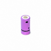
P-130SCR/A34
Description
BATTERY NICAD SC SIZE R TYPE
Manufacturer
Panasonic - BSG
Datasheet
1.P-130SCRF2.pdf
(87 pages)
Specifications of P-130SCR/A34
Battery Cell Size
SC - Flat Top
Voltage - Rated
1.2V
Capacity
1300mAh
Rechargeability
Yes
Termination Style
Flat Top (Non-Extending)
Internal Resistance
*
Standard Charge Time
*
Standard Charge Current
*
Weight
1.66 oz (47.06g)
Lead Free Status / RoHS Status
Lead free / RoHS compliant by exemption
Size / Dimension
-
Other names
P-130SCR
P-130SCR/FT
P159
P-130SCR/FT
P159


•
CHARGE METHODS FOR NI-CD BATTERIES - CONTINUED
(2) Features
This method is rarely used today, and it is not appro-
priate for the charge control system for Ni-Cd batter-
ies.
Matching the charger to the batteries is extremely
difficult, and if the detection voltage of the charger is
not set correctly, insufficient charge or overcharge
(thermal runaway) can easily occur.
General Specifications
(3) Precautions
•
A
C
i r T
p
h
N
The charge voltage increases in batteries which
have been left unused for a long period of time,
and during charge the charge voltage will quickly
reach the charger’s detection voltage. Therefore,
if the voltage-controlled charge control system is
used to charge batteries which have not been
used for a long period of time, the charge level will
be low. Matching the charger to the batteries is
extremely difficult, and if the detection voltage of
the charger is not set correctly, insufficient charge
p
The setting of the detection voltage is extremely
difficult. The setting of the detection voltage and
of the temperature compensation must be done
carefully, taking into consideration the variations
and fluctuations of the batteries and of the
charger as indicated below, and in order to avoid
overcharge (thermal runaway), the detection
voltage is generally set for insufficient charge.
Batteries: Single-cell and multi-cell (battery pack)
variations in the charge voltage, and fluctuation of
the charge voltage caused by the ambient
temperature.
Charger: Variations in the adjustment of the set
detection voltage, and fluctuation of the detection
voltage caused by the ambient temperature.
a
k c
D
O
c i l
u
g r
C
e
m
S
e l
u
C
h
e
a
e t
p t
a
b
a
h
b
C
e f
L
t c
r e
g r
a
t u
C
e l
e
h
g r
o i
y t
o
e
v
a
f o
T
B
n
n
e
l e
r e
g r
D
C
t a
r t
C
V
i T
e
m
l o
e
t a
r u
e t
o
h
v
m
n i
e r
C
a t l
c i
y r
a
V
e
a
g r
r u
e
t n
o
g
T
s l
a t l
e r
r e
e
p y
t n
g
e
e
s
m
N (
1
d
f i
a
T
t o
c i f
o t
h
n i
D (
r e
e r
t l u
c
2
e
m
h
c
c
e t
T
h
a
o
e
a
o
S
o
y
m
g r
e v
t c
p l
m
NICKEL CADMIUM HANDBOOK, PAGE 19
p
u
C
0
e t
p
A
o i
p
e
s r
m
5 .
n
e
o r
0
d
c i
p
m
e
n
c
c
0 .
e
i w
p
~
s n
c (
e t
b
p
l a
o
i t
n
f i
o r
o v
1
5
a
e
h t
m
t n
o
t c
d
a
c i
0 .
2
t t
. x
a r
G
m
C
a t l
e
o r
e t
) e
r o
r e
a
t a
d
C
u t
m
e
p
7
d
g
s l
e i
o l
e l
+
n
m
0
e r
f
o i
e
A
r o
f
%
s y
s
n
r o
r e
e t
A
o t
) .
m
n
) .
g
s u
e t
a t
r e
l a
s
c
u
h t
t s
m
h
i t l
e
e
a
c
b
a
g r
h
f
m
r o
a
s
e
e
r e
g r
h t
N
s i
e
e
- i
V-taper Controlled Charge System
This is the charge control method recommended for
Sealed Lead Acid batteries, and it is not recommended
for charge Ni-Cd batteries.
(1) Mechanism
This system is basically the same as the voltage-
controlled charge system already described. However,
in the V-taper controlled charge system, after the set
voltage is detected at the completion of charge, the
rapid charge current is supplied as a tapered current,
decreased at a predetermined rate over a predeter-
mined length of time, and then switched to trickle
current. Supplying the decreasing taper current makes
it possible to achieve a higher charge level than with the
voltage-controlled charge system.
Fig. 12 Charge Characteristics of the V-taper Controlled
or overcharge (thermal runaway) can easily occur.
Therefore, this method should never be used as the
main charge control system for Ni-Cd batteries.
Fig. 13 Circuit Block Diagram of the V-taper Controlled
V
I
ch
B
Charge System
0
Charge System
Voltage-Controlled
Charge System
Current
Controller
V-1
Con-
ver ter
Total Timer
I
V
ch
B
Timer
CR
T.P.: Thermal Protector
Voltage
T.: Thermistor
Switch
FEBRUARY 2002
V-taper Controlled
Charge System
T
T.P.
t
Related parts for P-130SCR/A34
Image
Part Number
Description
Manufacturer
Datasheet
Request
R


Part Number:
Description:
P-CHANNEL 12-V (D-S) MOSFET
Manufacturer:
Vishay
Datasheet:


Part Number:
Description:
BATTERY LITHIUM COIN 3V 20MM
Manufacturer:
Panasonic - BSG
Datasheet:

Part Number:
Description:
BATTERY LITHIUM COIN 90MAH 20MM
Manufacturer:
Panasonic - BSG
Datasheet:

Part Number:
Description:
BATTERY LITHIUM COIN 3V 16MM
Manufacturer:
Panasonic - BSG
Datasheet:

Part Number:
Description:
BATTERY LITHIUM COIN 3V 10MM
Manufacturer:
Panasonic - BSG
Datasheet:

Part Number:
Description:
BATTERY LITHIUM COIN 3V CELL
Manufacturer:
Panasonic - BSG
Datasheet:

Part Number:
Description:
BATTERY LITHIUM COIN STD 3V 23MM
Manufacturer:
Panasonic - BSG
Datasheet:

Part Number:
Description:
BATTERY LITHIUM COIN STD 3V 24MM
Manufacturer:
Panasonic - BSG
Datasheet:

Part Number:
Description:
BATTERY LITHIUM COIN 3V 24MM
Manufacturer:
Panasonic - BSG
Datasheet: