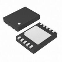
DS2786G+ Maxim Integrated Products, DS2786G+ Datasheet

DS2786G+
Specifications of DS2786G+
Related parts for DS2786G+
DS2786G+ Summary of contents
Page 1
... Interface Low Power Consumption: Active Current: 50A typ, 80A max Sleep Current: 1A typ, 3A max ORDERING INFORMATION PART DS2786G+ DS2786G+T&R +Denotes a lead(Pb)-free/RoHS-compliant package. T&R = Tape and reel. *EP = Exposed pad. PIN CONFIGURATION DS2786 Fuel Gauge = 15m) SNS = 15m ...
Page 2
ABSOLUTE MAXIMUM RATINGS Voltage Range on All Pins Except V Voltage Range on V Relative to V PROG Operating Temperature Range Storage Temperature Range Soldering Temperature This is a stress rating only and functional operation of the device at these ...
Page 3
PARAMETER SYMBOL V Precharge Time OUT Temperature Error T Input Logic High: SCL, SDA Input Logic Low: SCL, SDA Output Logic Low: SDA Pulldown Current: SCL, SDA V Pulldown R PROG Input Capacitance: C SCL, SDA Bus Low Timeout t ...
Page 4
PARAMETER SYMBOL Spike Pulse Widths t Suppressed by Input Filter Capacitive Load for Each C Bus Line SCL, SDA Input C Capacitance All voltages are referenced to V Note 1: Offset specified after auto-calibration cycle and Current Offset Bias Register ...
Page 5
PIN DESCRIPTION PIN NAME 1 AIN1 Aux Voltage Input Number 1 2 AIN0 Aux Voltage Input Number 0 Serial Clock Input. Input only 2-wire clock line. Connect this pin to the clock signal of the 3 SCL 2-wire interface. This ...
Page 6
DESCRIPTION The DS2786 provides current-flow, voltage, and temperature measurement data to support battery-capacity monitoring in cost-sensitive applications. Current is measured bidirectionally over a dynamic range of ±51.2mV with a resolution of 25µV. Assuming a 15m sense resistor, the current sense ...
Page 7
POWER MODES The DS2786 operates in one of two power modes: Active and Sleep. While in Active mode, the DS2786 operates as a high-precision battery monitor with temperature, voltage, auxiliary inputs, current, and accumulated current measurements acquired continuously and the ...
Page 8
VOLTAGE MEASUREMENT Battery voltage is measured at the V 1.22mV. The result is updated every 880ms and placed in the Voltage Register in two’s complement form. Voltages above the maximum register value are reported as 7FFFh. Figure 5. Voltage Register ...
Page 9
TEMPERATURE MEASUREMENT The DS2786 uses an integrated temperature sensor to measure battery temperature with a resolution of 0.125°C. Temperature measurements are updated every 1760ms and placed in the Temperature Register in two’s complement form. The format of the Temperature Register ...
Page 10
Table 1. Current Range and Resolution for Various R CURRENT RESOLUTION (1 LSB 25V CURRENT INPUT RANGE ±51.2mV CURRENT OFFSET BIAS The Current Offset Bias Register (COBR) allows a programmable offset value ...
Page 11
CELL CAPACITY ESTIMATION The DS2786 uses a hybrid OCV measurement and coulomb counting algorithm to estimate remaining cell capacity. During periods of charging or discharging of the cell, the DS2786 counts charge flow into and out of the cell. When ...
Page 12
OCV DETECTION AND CURRENT BLANKING The Blanking/OCV Threshold Register sets the current measurement level at which the DS2786 switches between coulomb counting and open-circuit voltage measurement. When the magnitude of the measured current (after COBR is applied) is less than ...
Page 13
OCV CELL MODEL The OCV cell model is a 9-point piece-wise linear approximation of open circuit cell voltage versus the remaining capacity of the cell. Whenever an OCV update occurs, the Relative Capacity Register is adjusted to a new value ...
Page 14
Figure 17. Voltage Breakpoint Register Format MSB—Even Addresses 68h–78h MSb “X”: reserved INITIAL CAPACITY ESTIMATION The DS2786 calculates Relative Capacity immediately upon power up. During initialization, the DS2786 makes a voltage measurement ...
Page 15
Figure 19. Last OCV Register Format The Learn Delta Percent Threshold allows the application to select how large of a cell capacity change is required before the new cell capacity value is learned. The difference between the present OCV measurement ...
Page 16
Table 3. Memory Map ADDRESS (HEX) 00h 01h 02h 03h to 07h 08h 09h 0Ah 0Bh 0Ch 0Dh 0Eh 0Fh 10h to 13h 14h 15h 16h 17h 18h to 5Fh 60h to 7Fh 80h to FDh Feh FFh Table 4. ...
Page 17
STATUS/CONFIG REGISTER The Status/Config Register is read/write with individual bits designated as read only. Bit values indicate status as well as program or select device functionality. Bits 3 though 6 are EEPROM backed at memory location 7Ch. Note that their ...
Page 18
COMMAND REGISTER The Command Register is read/write accessible. Bit values indicate operations requested to be performed by the device. Figure 23. Command Register Format BIT 7 BIT 6 POR 0 Bit 7: POR—Power-On Reset. A value of 1 starts a ...
Page 19
Bus Idle The bus is defined to be idle, or not busy, when no master device has control. Both SDA and SCL remain high when the bus is idle. The STOP condition is the proper method to return the bus ...
Page 20
Read/Write Bit The R/W bit following the slave address determines the data direction of subsequent bytes in the transfer. R selects a write transaction, with the following bytes being written by the master to the slave. R/W = ...
Page 21
Write Data Protocol The write data protocol is used to write to register and shadow RAM data to the DS2786 starting at memory address Maddr. Data0 represents the data written to Maddr, Data1 represents the data written to Maddr + ...
Page 22
... No circuit patent licenses are implied. Maxim/Dallas Semiconductor reserves the right to change the circuitry and specifications without notice at any time The Maxim logo is a registered trademark of Maxim Integrated Products, Inc. The Dallas logo is a registered trademark of Dallas Semiconductor Corporation. DESCRIPTION maximum operating range in the voltage” ...


