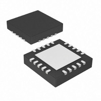
MCP73871-2CAI/ML Microchip Technology, MCP73871-2CAI/ML Datasheet - Page 16

MCP73871-2CAI/ML
Manufacturer Part Number
MCP73871-2CAI/ML
Description
IC USB/AC BATT CHRGR W/PPM 20QFN
Manufacturer
Microchip Technology
Specifications of MCP73871-2CAI/ML
Battery Type
Lithium-Ion (Li-Ion), Lithium-Polymer (Li-Pol)
Function
Charge Management
Voltage - Supply
4.4 V ~ 6 V
Operating Temperature
-40°C ~ 85°C
Mounting Type
Surface Mount
Package / Case
20-VFQFN Exposed Pad
Input Voltage
6V
Battery Charge Voltage
4.5V
Charge Current Max
1A
Battery Ic Case Style
QFN
No. Of Pins
20
No. Of Series Cells
1
Product
Charge Management
Output Voltage
4.2 V
Output Current
50 mA to 1000 mA
Operating Supply Voltage
4.5 V to 6 V
Maximum Operating Temperature
+ 85 C
Minimum Operating Temperature
- 40 C
Mounting Style
SMD/SMT
Lead Free Status / RoHS Status
Lead free / RoHS Compliant
For Use With
MCP73871DM-VPCC - DEMO BOARD FOR MCP73871MCP73871EV - EVALUATION BOARD FOR MCP73871
Lead Free Status / Rohs Status
Lead free / RoHS Compliant
Available stocks
Company
Part Number
Manufacturer
Quantity
Price
Company:
Part Number:
MCP73871-2CAI/ML
Manufacturer:
MICROCHIP
Quantity:
12 000
Part Number:
MCP73871-2CAI/ML
Manufacturer:
MICROCHIP/微芯
Quantity:
20 000
MCP73871
The voltage divider equation is shown below:
The calculated R
selected for R
to build the voltage divider for VPCC.
FIGURE 3-1:
3.4
The input source type selection (SEL) pin is used to
select input power source for input current limit control
feature. With the SEL input High, the MCP73871
device is designed to provide a typical 1.65A to system
power and charge Li-Ion battery from a regular 5V wall
adapter. The MCP73871 device limits the input current
up to 1.8A. When SEL active Low, the input source is
designed to provide system power and Li-Ion battery
charging from a USB Port input while adhering to the
current limits governed by the USB specification.
3.5
Connect to negative terminal of battery, system load
and input supply.
3.6
Connect to positive terminal of Li-Ion / Li-Polymer
batteries. Bypass to V
ensure loop stability when the battery is disconnected.
3.7
Connect to positive terminal of battery. A precision
internal voltage sense regulates the final voltage on
this pin to V
DS22090B-page 16
Input Source Type Selection (SEL)
Battery Management 0V Reference
(V
Battery Charge Control Output
(V
Battery Voltage Sense
(V
V
VPCC
SS
BAT
BAT_SENSE
REG
1.23V
2
330 kΩ
110 kΩ
)
. The 330 kΩ resistor is selected for R
.
)
1
=
R
equals to 337.2 kΩ when 110 kΩ is
=
1
⎛
⎝
------------------ -
R
=
V
⎛
⎝
SS
Voltage Divider Example.
1
----------------------------- -
110k
IN
R
+
337.2kΩ
)
2
with a minimum of 4.7 µF to
110k
R
2
Ω
⎞
⎠
×
+
Ω
V
R
IN
VPCC
1
⎞
⎠
=
×
5V
1.23V
1
3.8
The maximum constant charge current is set by placing
a resistor from PROG1 to V
maximum constant charge current for both ac-dc
adapter and USB port. However, the actual charge
current is based on input source type and system load
requirement.
3.9
The MCP73871 device USB-Port current regulation set
input (PROG2) is a digital input selection. A logic Low
selects a 1 unit load input current from USB port
(100 mA); a logic High selects a 5 unit loads input
current from USB port (500 mA).
3.10
STAT1 is an open-drain logic output for connection to
an LED for charge status indication. Alternatively, a
pull-up resistor can be applied for interfacing to a host
microcontroller. Refer to
status output during a charge cycle.
3.11
STAT2 is an open-drain logic output for connection to
an LED for charge status indication. Alternatively, a
pull-up resistor can be applied for interfacing to a host
microcontroller. Refer to
status output during a charge cycle.
3.12
The power-good (PG) is an open-drain logic output for
input power supply indication. The PG output is low
whenever the input to the MCP73871 device is above
the UVLO threshold and greater than the battery
voltage. The PG output can be used as an indication to
the user via an illuminated LED or to the system via a
pull-up resistor for interfacing to a host microcontroller
that an input source other than the battery is supplying
power. Refer to
output during a charge cycle.
3.13
STAT1 also serves as low battery output (LBO) if the
selected MCP73871 is equipped with this feature. It
reminds the system or end user when the Li-Ion battery
voltage level is low. The LBO feature enables when the
system is running from the Li-Ion batteries. The LBO
indicator can be used as an indication to the user via lit
up LED or to the system via a pull-up resistor for
interfacing to a host microcontroller that an input
source other than the battery is supplying power. Refer
to
a charge cycle.
Table 5-1
Charge Current Regulation Set
(PROG1)
USB-Port Current Regulation Set
(PROG2)
Charge Status Output 1 (STAT1)
Charge Status Output 2 (STAT2)
Power-Good (PG)
Low Battery Output (LBO)
for a summary of the status output during
Table 5-1
© 2009 Microchip Technology Inc.
Table 5-1
Table 5-1
for a summary of the status
SS
for a summary of the
for a summary of the
. PROG1 sets the


