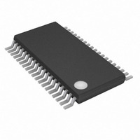
MAX11080GUU+ Maxim Integrated Products, MAX11080GUU+ Datasheet - Page 22

MAX11080GUU+
Manufacturer Part Number
MAX11080GUU+
Description
IC LI/BATTERY MANAGEMENT 38TSSOP
Manufacturer
Maxim Integrated Products
Specifications of MAX11080GUU+
Function
Battery Monitor
Battery Type
Lithium-Ion (Li-Ion)
Voltage - Supply
6 V ~ 72 V
Operating Temperature
-40°C ~ 105°C
Mounting Type
Surface Mount
Package / Case
38-TSSOP (0.173", 4.40mm Width)
Product
Charge Management
Operating Supply Voltage
6 V to 72 V
Supply Current
0.05 uA
Maximum Operating Temperature
+ 105 C
Minimum Operating Temperature
- 40 C
Charge Safety Timers
No
Mounting Style
SMD/SMT
Temperature Monitoring
No
Uvlo Start Threshold
1.6 V
Uvlo Stop Threshold
2.8 V
No. Of Batteries
12
Supply Voltage Range
6V To 72V
Battery Ic Case Style
TSSOP
No. Of Pins
38
Operating Temperature Range
-40°C To +105°C
Rohs Compliant
Yes
Lead Free Status / RoHS Status
Lead free / RoHS Compliant
12-Channel, High-Voltage
Battery-Pack Fault Monitors
Table 3. System Fault Modes
22
PCB or IC package open or short
circuit—no stack load
Random connection of cells to IC—
no stack load
Random connection of modules—
no stack load
Random connect/disconnect of
communication bus—no stack load;
AC- or DC-coupled
Random connect/disconnect of
communication bus—with stack load;
AC- or DC-coupled
Connect/disconnect module
interconnect (bus bar)—no stack load
Removal/fault of module interconnect
(bus bar)—with stack load
Removal/fault of module interconnect
(bus bar)—with stack under charge
______________________________________________________________________________________
CONDITION
Refer to the pin-level FMEA analysis
spreadsheet available from the factory
No effect
No effect
Communication from host to the first
break in the daisy-chain bus
Communication from host to the first
break in the daisy-chain bus
No effect for DC- or AC-coupled
communication bus
No effect for AC-coupled
communication bus; device damage for
DC-coupled bus
No effect for AC-coupled
communication bus; device damage for
DC-coupled bus
EFFECT
The b ui l t- i n featur es of the
M AX 11080/M AX 11081, shoul d ensur e l ow FM E A
r i sk i n m ost cases.
The series resistors on the cell inputs of the
M AX 11080/M AX 11081, as well as the internal
design, ensure protection against random
power-supply or ground connections.
E ach m od ul e i s r efer enced to i ts nei g hb or , so no
sp eci al connecti on or d er i s necessar y.
The level-shifted interface design of the
M AX 11080/M AX 11081 ensures that the SHDN,
GND
connected at any time with no load.
The level-shifted interface design of the
M AX 11080/M AX 11081 ensures that the SHDN,
GND
connected at any time as long as the power
bus is properly connected.
A break in the power bus does not cause a
problem as long as there is no load on the
stack.
An AC-coupled bus with isolation on the SHDN
pin or a redundant bus-bar connection should
be used to protect against this case.
An AC-coupled bus with isolation on the SHDN
pin or a redundant bus-bar connection should
be used to protect against this case.
U
U
, and ALRM_ communication bus can be
, ALRM_ communication bus can be
DESIGN RECOMMENDATION


