MAX11080GUU+ Maxim Integrated Products, MAX11080GUU+ Datasheet - Page 5
MAX11080GUU+
Manufacturer Part Number
MAX11080GUU+
Description
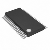
IC LI/BATTERY MANAGEMENT 38TSSOP
Manufacturer
Maxim Integrated Products
Specifications of MAX11080GUU+
Function
Battery Monitor
Battery Type
Lithium-Ion (Li-Ion)
Voltage - Supply
6 V ~ 72 V
Operating Temperature
-40°C ~ 105°C
Mounting Type
Surface Mount
Package / Case
38-TSSOP (0.173", 4.40mm Width)
Product
Charge Management
Operating Supply Voltage
6 V to 72 V
Supply Current
0.05 uA
Maximum Operating Temperature
+ 105 C
Minimum Operating Temperature
- 40 C
Charge Safety Timers
No
Mounting Style
SMD/SMT
Temperature Monitoring
No
Uvlo Start Threshold
1.6 V
Uvlo Stop Threshold
2.8 V
No. Of Batteries
12
Supply Voltage Range
6V To 72V
Battery Ic Case Style
TSSOP
No. Of Pins
38
Operating Temperature Range
-40°C To +105°C
Rohs Compliant
Yes
Lead Free Status / RoHS Status
Lead free / RoHS Compliant


3, 33
PIN
10
11
12
13
14
15
16
17
18
19
20
21
22
23
1
2
4
5
6
7
8
9
UVSEL0
UVSEL1
UVSEL2
OVSEL0
OVSEL1
OVSEL2
OVSEL3
NAME
DCIN
N.C.
C12
C11
C10
HV
C9
C8
C7
C6
C5
C4
C3
C2
C1
C0
_______________________________________________________________________________________
DC Power-Supply Input. DCIN supplies the internal 3.3V regulator. This pin should be connected as shown
in the application diagrams.
High-Voltage Bias. HV is biased by the output of the charge pump to provide a DC supply above the DCIN
level. It is used internally to bias the cell-comparator circuitry. Bypass to DCIN with a 1µF capacitor.
No Connection. Not internally connected.
Cell 12 Plus Connection. Top of battery module stack.
Cell 12 Minus Connection and Cell 11 Plus Connection
Cell 11 Minus Connection and Cell 10 Plus Connection
Cell 10 Minus Connection and Cell 9 Plus Connection
Cell 9 Minus Connection and Cell 8 Plus Connection
Cell 8 Minus Connection and Cell 7 Plus Connection
Cell 7 Minus Connection and Cell 6 Plus Connection
Cell 6 Minus Connection and Cell 5 Plus Connection
Cell 5 Minus Connection and Cell 4 Plus Connection
Cell 4 Minus Connection and Cell 3 Plus Connection
Cell 3 Minus Connection and Cell 2 Plus Connection
Cell 2 Minus Connection and Cell 1 Plus Connection
Cell 1 Minus Connection. Connect to AGND.
Undervoltage Threshold Select 0 to 2. Used to select one of eight undervoltage alarm threshold settings.
The parts have internal pulldown; these pins should only be tied to V
Overvoltage Threshold Select 0 to 3. Used to select one of 16 overvoltage alarm threshold settings.
The parts have internal pulldown; these pins should only be tied to V
Battery-Pack Fault Monitors
12-Channel, High-Voltage
FUNCTION
AA
AA
or AGND to set the logic state.
or AGND to set the logic state.
Pin Description
5
Related parts for MAX11080GUU+
Image
Part Number
Description
Manufacturer
Datasheet
Request
R

Part Number:
Description:
MAX7528KCWPMaxim Integrated Products [CMOS Dual 8-Bit Buffered Multiplying DACs]
Manufacturer:
Maxim Integrated Products
Datasheet:
Part Number:
Description:
Single +5V, fully integrated, 1.25Gbps laser diode driver.
Manufacturer:
Maxim Integrated Products
Datasheet:
Part Number:
Description:
Single +5V, fully integrated, 155Mbps laser diode driver.
Manufacturer:
Maxim Integrated Products
Datasheet:
Part Number:
Description:
VRD11/VRD10, K8 Rev F 2/3/4-Phase PWM Controllers with Integrated Dual MOSFET Drivers
Manufacturer:
Maxim Integrated Products
Datasheet:
Part Number:
Description:
Highly Integrated Level 2 SMBus Battery Chargers
Manufacturer:
Maxim Integrated Products
Datasheet:
Part Number:
Description:
Current Monitor and Accumulator with Integrated Sense Resistor; ; Temperature Range: -40°C to +85°C
Manufacturer:
Maxim Integrated Products
Part Number:
Description:
TSSOP 14/A�/RS-485 Transceivers with Integrated 100O/120O Termination Resis
Manufacturer:
Maxim Integrated Products
Part Number:
Description:
TSSOP 14/A�/RS-485 Transceivers with Integrated 100O/120O Termination Resis
Manufacturer:
Maxim Integrated Products
Part Number:
Description:
QFN 16/A�/AC-DC and DC-DC Peak-Current-Mode Converters with Integrated Step
Manufacturer:
Maxim Integrated Products
Part Number:
Description:
TDFN/A/65V, 1A, 600KHZ, SYNCHRONOUS STEP-DOWN REGULATOR WITH INTEGRATED SWI
Manufacturer:
Maxim Integrated Products
Part Number:
Description:
Integrated Temperature Controller f
Manufacturer:
Maxim Integrated Products
Part Number:
Description:
SOT23-6/I�/45MHz to 650MHz, Integrated IF VCOs with Differential Output
Manufacturer:
Maxim Integrated Products
Part Number:
Description:
SOT23-6/I�/45MHz to 650MHz, Integrated IF VCOs with Differential Output
Manufacturer:
Maxim Integrated Products
Part Number:
Description:
EVALUATION KIT/2.4GHZ TO 2.5GHZ 802.11G/B RF TRANSCEIVER WITH INTEGRATED PA
Manufacturer:
Maxim Integrated Products
Part Number:
Description:
QFN/E/DUAL PCIE/SATA HIGH SPEED SWITCH WITH INTEGRATED BIAS RESISTOR
Manufacturer:
Maxim Integrated Products
Datasheet: