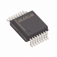
DS2437S Maxim Integrated Products, DS2437S Datasheet - Page 18

DS2437S
Manufacturer Part Number
DS2437S
Description
IC MONITOR SMART BATTERY 16-SSOP
Manufacturer
Maxim Integrated Products
Datasheet
1.DS2437S-3.pdf
(31 pages)
Specifications of DS2437S
Function
Battery Monitor
Battery Type
Smart Batteries
Voltage - Supply
2.7 V ~ 10 V
Operating Temperature
-40°C ~ 85°C
Mounting Type
Surface Mount
Package / Case
16-SSOP
Lead Free Status / RoHS Status
Contains lead / RoHS non-compliant
Available stocks
Company
Part Number
Manufacturer
Quantity
Price
Part Number:
DS2437S
Manufacturer:
MAXIM/美信
Quantity:
20 000
Search ROM [F0h]
When a system is initially brought up, the bus master might not know the number of devices on the
1-Wire bus or their 64-bit ROM codes. The search ROM command allows the bus master to use a process
of elimination to identify the 64-bit ROM codes of all slave devices on the bus.
Example of a ROM Search
The ROM search process is the repetition of a simple three-step routine: read a bit, read the complement
of the bit, then write the desired value of that bit. The bus master performs this simple, 3-step routine on
each bit of the ROM. After one complete pass, the bus master knows the contents of the ROM in one
device. The remaining number of devices and their ROM codes may be identified by additional passes.
The following example of the ROM search process assumes four different devices are connected to the
same 1-Wire bus. The ROM data of the four devices is as shown (LSb first):
The search process is as follows:
1. The bus master begins the initialization sequence by issuing a reset pulse. The slave devices respond
2. The bus master will then issue the search ROM command on the 1-Wire bus (F0h).
3. The bus master reads a bit from the 1-Wire bus. Each device will respond by placing the value of the
4. The bus master writes a 0. This deselects ROM2 and ROM3 for the remainder of this search pass,
5. The bus master performs two more reads and receives a 0-bit followed by a 1-bit. This indicates that
6. The bus master then writes a 0 to keep both ROM1 and ROM4 coupled.
7. The bus master executes two reads and receives two 0-bits. This indicates that both 1-bits and 0-bits
by issuing simultaneous presence pulses.
first bit of their respective ROM data onto the 1-Wire bus. ROM1 and ROM4 will place a 0 onto the
1-Wire bus, i.e., pull it low. ROM2 and ROM3 will place a 1 onto the 1-Wire bus by allowing the line
to stay high. The result is the logical AND of all devices on the line; therefore the bus master sees a 0.
The bus master reads another bit. Since the Search ROM data command is being executed, all of the
devices on the 1-Wire bus respond to this second read by placing the complement of the first bit of
their respective ROM data onto the 1-Wire bus. ROM1 and ROM4 will place a 1 onto the 1-wire,
allowing the line to stay high. ROM2 and ROM3 will place a 0 onto the 1-wire; thus it will be pulled
low. The bus master again observes a 0 for the complement of the first ROM data bit. The bus master
has determined that there are some devices on the 1-Wire bus that have a 0 in the first position and
others that have a 1.
The data obtained from the two reads of the three-step routine have the following interpretations:
00 - There are still devices attached which have conflicting bits in this position.
01 - All devices still coupled have a 0-bit in this bit position.
10 - All devices still coupled have a 1-bit in this bit position.
11 - There are no devices attached to the 1-Wire bus.
leaving only ROM1 and ROM4 connected to the 1-Wire bus.
all devices still coupled to the bus have 0s as their second ROM data bit.
exist as the 3
rd
bit of the ROM data of the attached devices.
ROM1 = 00110101...
ROM2 = 10101010...
ROM3 = 11110101...
ROM4 = 00010001...
18 of 31
DS2437


