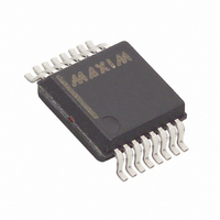
DS2437S/T&R Maxim Integrated Products, DS2437S/T&R Datasheet - Page 19

DS2437S/T&R
Manufacturer Part Number
DS2437S/T&R
Description
IC MONITOR SMART BATTERY 16-SSOP
Manufacturer
Maxim Integrated Products
Datasheet
1.DS2437S-3.pdf
(31 pages)
Specifications of DS2437S/T&R
Function
Battery Monitor
Battery Type
Smart Batteries
Voltage - Supply
2.7 V ~ 10 V
Operating Temperature
-40°C ~ 85°C
Mounting Type
Surface Mount
Package / Case
16-SSOP
Lead Free Status / RoHS Status
Contains lead / RoHS non-compliant
8. The bus master writes a 0-bit. This deselects ROM1 leaving ROM4 as the only device still connected.
9. The bus master reads the remainder of the ROM bits for ROM4 and continues to access the part if
10. The bus master starts a new ROM search sequence by repeating steps 1 through 7.
11. The bus master writes a 1-bit. This decouples ROM4, leaving only ROM1 still coupled.
12. The bus master reads the remainder of the ROM bits for ROM1 and communicates to the underlying
13. The bus master starts a new ROM search by repeating steps 1 through 3.
14. The bus master writes a 1-bit. This deselects ROM1 and ROM4 for the remainder of this search pass,
15. The bus master executes two read time slots and receives two 0s.
16. The bus master writes a 0-bit. This decouples ROM3, and leaving only ROM2.
17. The bus master reads the remainder of the ROM bits for ROM2 and communicates to the underlying
18. The bus master starts a new ROM search by repeating steps 13 through 15.
19. The bus master writes a 1-bit. This decouples ROM2, leaving only ROM3.
20. The bus master reads the remainder of the ROM bits for ROM3 and communicates to the underlying
Note that the bus master learns the unique ID number (ROM data pattern) of one 1-Wire device on each
ROM Search operation. The time required to derive the part’s unique ROM code is:
The bus master is therefore capable of identifying 75 different 1-Wire devices per second.
MEMORY COMMAND FUNCTIONS
The following command protocols are summarized in Table 6, and by the flowchart of Figure 6.
Write Scratchpad [4Ehxxh]
This command writes to the scratchpad page xxh of the DS2437. The entire 8-byte scratchpad space may
be written, but all writing begins with the byte present at address 0 of the selected scratchpad. After
issuing this command, the user must send the page number of the scratchpad to be written; then the user
may begin writing data to the DS2437 scratchpad. Writing may be terminated at any point by issuing a
reset. Valid page numbers for writing are 00h-07h.
Read Scratchpad [BEhxxh]
This command reads the contents of the scratchpad page xxh on the DS2437. After issuing this command,
the user must send the page number of the scratchpad to be read, and then may begin reading the data,
always beginning at address 0 of the selected scratchpad. The user may read through the end of the
scratchpad space (byte 07h), with any reserved data bits reading all logic 1s and after which the data read
will be all logic 1s. If not all locations are to be read, the master may issue a reset to terminate reading at
any time. Valid page numbers are 00h - 07h.
desired. This completes the first pass and uniquely identifies one part on the 1-Wire bus.
logic if desired. This completes the second ROM search pass, in which another of the ROMs was
found.
leaving only ROM2 and ROM3 coupled to the system.
logic if desired. This completes the third ROM search pass, in which another of the ROMs was found.
logic if desired. This completes the fourth ROM search pass, in which another of the ROMs was
found.
960 µs + (8 + 3 x 64) 61 µs = 13.16 ms
19 of 31
DS2437


