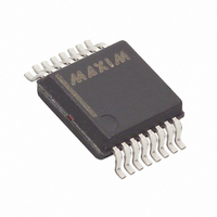
DS2437S-3/T&R Maxim Integrated Products, DS2437S-3/T&R Datasheet - Page 20

DS2437S-3/T&R
Manufacturer Part Number
DS2437S-3/T&R
Description
IC MONITOR SMART BATTERY 16-SSOP
Manufacturer
Maxim Integrated Products
Datasheet
1.DS2437S-3.pdf
(31 pages)
Specifications of DS2437S-3/T&R
Function
Battery Monitor
Battery Type
Smart Batteries
Voltage - Supply
2.7 V ~ 10 V
Operating Temperature
-40°C ~ 85°C
Mounting Type
Surface Mount
Package / Case
16-SSOP
Lead Free Status / RoHS Status
Contains lead / RoHS non-compliant
Copy Scratchpad [48hxxh]
This command copies the scratchpad page xxh into the EEPROM / SRAM memory page xxh of the
DS2437. After issuing this command, the user must write a page number to direct which page of memory
the scratchpad is to be copied. Valid page numbers are 00h - 07h. If the bus master issues read time slots
following this command, the DS2437 will output 0 on the bus as long as it is busy copying the scratchpad
to SRAM/EEPROM; it will return a 1 when the copy process is complete.
Recall Memory [B8hxxh]
This command recalls the stored values in EEPROM/SRAM page xxh to the scratchpad page xxh. This
command must procede a Read SPxx command in order to read any page of memory on the DS2437. No
data is available directly with a Read SP command. Valid page numbers are 00h - 07h.
Convert T [44h]
This command begins a temperature conversion. No further data is required. The temperature conversion
will be performed and then the DS2437 will remain idle. If the bus master issues read time slots
following this command, the DS2437 will output 0 on the bus as long as it is busy making a temperature
conversion; it will return a 1 when the temperature conversion is complete.
Convert V [B4h]
This command instructs the DS2437 to initiate a voltage analog-to-digital conversion cycle. The voltage
supply that is measured is defined by the AD bit of the Status/Configuration register. This sets the ADB
flag (see Status/Configuration register discussion in the Memory Map section). When the A/D conversion
is done, the ADB flag is cleared and the current voltage value is placed in the VOLTAGE REGISTER of
page 00h. While an A/D conversion is taking place, all other memory functions are still available for use.
If the bus master issues read time slots following this command, the DS2437 will output 0 on the bus as
long as it is busy making a voltage measurement; it will return a 1 when the conversion is complete.
DS2437 COMMAND SET Table 6
INSTRUCTION
Write Scratchpad
Copy Scratchpad
Read Scratchpad
Recall Memory
Copies entire contents
Copies entire contents
Scratchpad page xxh
of EEPROM/SRAM
DS2437 Scratchpad
DS2437 Scratchpad
of Scratchpad page
EEPROM/SRAM
Reads bytes from
DESCRIPTION
xxh to eight-byte
Writes bytes to
page xxh to
page xxh
page xxh
page xxh
MEMORY COMMANDS
PROTOCOL
BEh <page
00h-07Fh>
4Eh <page
B8h<page
00h-07h>
48h<page
00h-07h>
00h-07h>
20 of 31
STATUS AFTER
Idle or Rx of
1-WIRE BUS
PROTOCOL
MASTER
ISSUING
NVB bit
Idle
Rx
Tx
Register = 1 until copy
1-WIRE BUS DATA
<read up to nine bytes
AFTER ISSUING
complete (2-10 ms,
{NVB bit in Status
<write up to eight
PROTOCOL
bytes of data>
of data>
typ)}
Idle
DS2437


