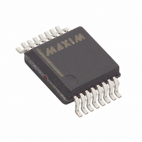
DS2437S-3/T&R Maxim Integrated Products, DS2437S-3/T&R Datasheet - Page 7

DS2437S-3/T&R
Manufacturer Part Number
DS2437S-3/T&R
Description
IC MONITOR SMART BATTERY 16-SSOP
Manufacturer
Maxim Integrated Products
Datasheet
1.DS2437S-3.pdf
(31 pages)
Specifications of DS2437S-3/T&R
Function
Battery Monitor
Battery Type
Smart Batteries
Voltage - Supply
2.7 V ~ 10 V
Operating Temperature
-40°C ~ 85°C
Mounting Type
Surface Mount
Package / Case
16-SSOP
Lead Free Status / RoHS Status
Contains lead / RoHS non-compliant
The ICA is a scaled 8-bit (0.01C resolution) volatile binary counter which represents the amount of
capacity remaining in the battery in terms of the full capacity (1C), normalized to a count of 100
an ICA count of 100
represents 0% of capacity or fully discharged. The ICA will count up to 255
incremented above 2.55C, which should not occur during charging. However, since charging typically
provides the battery with more than its rated capacity, the ICA should be reset to a count of 100
charging is complete to indicate that the battery is at 100% of capacity and to ensure that later gas gauge
measurements are accurate.
The ICA is only incremented/decremented if the IAD bit is set to 1 in the CONFIGURATION
REGISTER. Refer to the “Memory Map” section for details of device configuration. Table 4 below
illustrates the contents of the ICA. See Memory Map section for the address location of the ICA.
ICA/Data Relationships Table 4
The Charging Current Accumulator (CCA) is a 2-byte (0.32C resolution) nonvolatile read/write counter
which represents the total charging current the battery has encountered in its lifetime. It is only updated
when current through R
register, the information will accumulate over the lifetime of the battery pack and will not be lost when
the battery becomes discharged.
Similarly, the Discharge Current Accumulator (DCA) is a 2-byte nonvolatile counter which represents the
total discharging current the battery has encountered over its lifetime. It features the same resolution as
the CCA and it also is shadowed to EEPROM in the background at the rate of once per 0.32C of
discharge current if the DS2437 is properly configured, thus allowing three EEPROM updates for each
complete discharge cycle of the battery pack. Table 5 illustrates the contents of the CCA/DCA registers.
In reference to the CCA/DCA, the DS2437 can be configured to function in any of three modes. Refer to
the Memory Map section for details of device configuration and for the address location of the
CCA/DCA.
1. The CCA/DCA is disabled. Charging/discharging current will not be accumulated, thus allowing free
2. The CCA/DCA will accumulate charging/discharging current, but the information will NOT be
use of EEPROM page 07h otherwise reserved for the CCA/DCA.
shadowed to EEPROM. The information could be lost or corrupted upon discharge of the battery
(depending upon the voltage to which discharged battery decays). The memory location is reserved
for the CCA/DCA, and the entire page SHOULD NOT be written to.
CAPACITY
BATTERY
2.55C
1.0C
0.5C
0.1C
0C
10
represents 1C of charge or 100% of capacity or fully charged, while a count of 0
SENS
is positive; i.e., the battery is being charged. Because this is a nonvolatile
DIGITAL OUTPUT (Binary)
1111 1111
0110 0100
0011 0010
0000 1010
0000 0000
7 of 31
DIGITAL OUTPUT (Hex)
10
, but will not roll over if
0Ah
FFh
64h
32h
00h
10
10
. Thus,
DS2437
when


