MM74C928N Fairchild Semiconductor, MM74C928N Datasheet
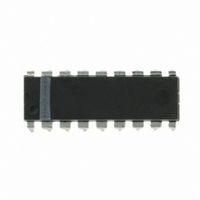
IC COUNTER 4DIG 7SEG DRVR 18-DIP

MM74C928N

Manufacturer Part Number
MM74C928N
Description
IC COUNTER 4DIG 7SEG DRVR 18-DIP
Manufacturer
Fairchild Semiconductor
Datasheet

Specifications of MM74C928N

Display Type
LED
Configuration
7 Segment
Interface
BCD
Digits Or Characters
4 Digits
Current - Supply
20µA
Voltage - Supply
3 V ~ 6 V
Operating Temperature
-40°C ~ 85°C
Mounting Type
Through Hole
Package / Case
18-DIP (0.300", 7.62mm)
Lead Free Status / RoHS Status
Contains lead / RoHS non-compliant
Other names
74C928
74C928N

Available stocks

Company
Part Number
Manufacturer
Quantity
Price
Part Number:
MM74C928N
Quantity:
2 943
Part Number:
MM74C928N
Manufacturer:
NS/国半
Quantity:
20 000
© 1999 Fairchild Semiconductor Corporation
MM74C925N
MM74C926N
MM74C927N
MM74C928N
MM74C925 • MM74C926 • MM74C927 • MM74C928
4-Digit Counters with Multiplexed
7-Segment Output Drivers
General Description
The MM74C925, MM74C926, MM74C927 and MM74C928
CMOS counters consist of a 4-digit counter, an internal out-
put latch, NPN output sourcing drivers for a 7-segment dis-
play, and an internal multiplexing circuitry with four
multiplexing outputs. The multiplexing circuit has its own
free-running oscillator, and requires no external clock. The
counters advance on negative edge of clock. A HIGH sig-
nal on the Reset input will reset the counter to zero, and
reset the carry-out LOW. A LOW signal on the Latch
Enable input will latch the number in the counters into the
internal output latches. A HIGH signal on Display Select
input will select the number in the counter to be displayed;
a LOW level signal on the Display Select will select the
number in the output latch to be displayed.
The MM74C925 is a 4-decade counter and has Latch
Enable, Clock and Reset inputs.
The MM74C926 is like the MM74C925 except that it has a
display select and a carry-out used for cascading counters.
The carry-out signal goes HIGH at 6000, goes back LOW
at 0000.
The MM74C927 is like the MM74C926 except the second
most significant digit divides by 6 rather than 10. Thus, if
the clock input frequency is 10 Hz, the display would read
tenths of seconds and minutes (i.e., 9:59.9).
The MM74C928 is like the MM74C926 except the most sig-
nificant digit divides by 2 rather than 10 and the carry-out is
an overflow indicator which is HIGH at 2000, and it goes
Ordering Code:
Order Number
Package Number
N16E
N18A
N18A
N18A
16-Lead Plastic Dual-In-Line Package (PDIP), JEDEC MS-001, 0.300” Wide
18-Lead Plastic Dual-In-Line Package (PDIP), JEDEC MS-001, 0.300” Wide
DS005919.prf
back LOW only when the counter is reset. Thus, this is a
3½-digit counter.
Features
Design Considerations
Segment resistors are desirable to minimize power dissipa-
tion and chip heating. The DS75492 serves as a good digit
driver when it is desired to drive bright displays. When
using this driver with a 5V supply at room temperature, the
display can be driven without segment resistors to full illu-
mination. The user must use caution in this mode however,
to prevent overheating of the device by using too high a
supply voltage or by operating at high ambient tempera-
tures.
The input protection circuitry consists of a series resistor,
and a diode to ground. Thus input signals exceeding V
will not be clamped. This input signal should not be allowed
to exceed 15V.
Wide supply voltage range:
Guaranteed noise margin: 1V
High noise immunity: 0.45 V
High segment sourcing current: 40 mA
@ V
Internal multiplexing circuitry
CC
Package Description
1.6V, V
CC
5V
October 1987
Revised January 1999
CC
3V to 6V
(typ.)
www.fairchildsemi.com
CC

Related parts for MM74C928N

MM74C928N Summary of contents

Page 1

... Plastic Dual-In-Line Package (PDIP), JEDEC MS-001, 0.300” Wide MM74C927N N18A 18-Lead Plastic Dual-In-Line Package (PDIP), JEDEC MS-001, 0.300” Wide MM74C928N N18A 18-Lead Plastic Dual-In-Line Package (PDIP), JEDEC MS-001, 0.300” Wide © 1999 Fairchild Semiconductor Corporation back LOW only when the counter is reset. Thus, this is a 3½ ...

Page 2

Connection Diagrams Top View MM74C925 Functional Description Reset — Asynchronous, active high Display Select — High, displays output of counter Low, displays output of latch Latch Enable — High, flow through condition Low, latch condition Clock —Negative edge sensitive Logic ...

Page 3

Logic Diagrams (Continued) MM74C926 MM74C927 MM74C928 3 www.fairchildsemi.com ...

Page 4

Absolute Maximum Ratings Voltage at Any Output Pin GND 0. Voltage at Any Input Pin GND Operating Temperature Range ( Storage Temperature Range Power Dissipation (P ) Refer D(MAX) DC Electrical Characteristics Min/Max ...

Page 5

AC Electrical Characteristics pF, unless otherwise noted A L Symbol Parameter f Maximum Clock Frequency MAX Maximum Clock Rise or Fall Time Reset Pulse Width WR t Latch Enable ...

Page 6

Typical Performance Characteristics Segment Output Driver www.fairchildsemi.com (Continued) Input Protection Common Cathode LED Display Segment Identification 6 ...

Page 7

Switching Time Waveforms Input Waveforms Multiplexing Output Waveforms T 1/f MUX Carry-Out Waveforms 7 www.fairchildsemi.com ...

Page 8

Physical Dimensions inches (millimeters) unless otherwise noted 16-Lead Plastic Dual-In-Line Package (PDIP), JEDEC MS-001, 0.300” Wide www.fairchildsemi.com Package Number N16E 8 ...

Page 9

Physical Dimensions inches (millimeters) unless otherwise noted (Continued) 18-Lead Plastic Dual-In-Line Package (PDIP), JEDEC MS-001, 0.300” Wide LIFE SUPPORT POLICY FAIRCHILD’S PRODUCTS ARE NOT AUTHORIZED FOR USE AS CRITICAL COMPONENTS IN LIFE SUPPORT DEVICES OR SYSTEMS WITHOUT THE EXPRESS WRITTEN ...

Related keywords