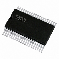
PCF8566T/1,118 NXP Semiconductors, PCF8566T/1,118 Datasheet - Page 8

PCF8566T/1,118
Manufacturer Part Number
PCF8566T/1,118
Description
IC LCD DVR UNVRSL LOW-MUX 40VSOP
Manufacturer
NXP Semiconductors
Datasheet
1.PCF8566T1118.pdf
(48 pages)
Specifications of PCF8566T/1,118
Package / Case
40-VSOP
Display Type
LCD
Configuration
7 Segment + DP, 14 Segment (24 Segment)
Interface
I²C
Current - Supply
30µA
Voltage - Supply
2.5 V ~ 6 V
Operating Temperature
-40°C ~ 85°C
Mounting Type
Surface Mount
Number Of Digits
12
Number Of Segments
96
Maximum Clock Frequency
315 KHz
Operating Supply Voltage
2.5 V to 6 V
Maximum Power Dissipation
400 mW
Maximum Operating Temperature
+ 85 C
Maximum Supply Current
90 uA
Minimum Operating Temperature
- 40 C
Lead Free Status / RoHS Status
Lead free / RoHS Compliant
Digits Or Characters
-
Lead Free Status / Rohs Status
Lead free / RoHS Compliant
Other names
568-1070-2
935278688118
PCF8566TD-T
935278688118
PCF8566TD-T
NXP Semiconductors
Table 5.
PCF8566_7
Product data sheet
LCD drive mode Number of:
static
1:2 multiplex
1:2 multiplex
1:3 multiplex
1:4 multiplex
Preferred LCD drive modes: summary of characteristics
Backplanes
1
2
2
3
4
A practical value for V
threshold voltage (V
the static drive mode a suitable choice is V
Multiplex drive modes of 1:3 and 1:4 with
hence the contrast ratios are smaller.
Bias is calculated by
The RMS on-state voltage (V
where V
The RMS off-state voltage (V
Discrimination is the ratio of V
Using
V
V
----------------------- -
V
V
•
on RMS
off RMS
a = 1 for
a = 2 for
n = 1 for static mode
n = 2 for 1:2 multiplex
n = 3 for 1:3 multiplex
n = 4 for 1:4 multiplex
off RMS
on RMS
1:3 multiplex with
Equation
LCD
Bias levels
2
3
4
4
4
=
=
=
1
1
2
3
V
is the resultant voltage at the LCD segment and where the values for n are
V
bias
bias
LCD
LCD
------------------------------------------- -
a
a 1
3, the discrimination for an LCD drive mode of
----------------------------------------------------------- -
+
1
-- -
n
–
a
-------------------------------- -
n
+
2
1
th
–
------------ -
1
), typically when the LCD exhibits approximately 10 % contrast. In
Rev. 07 — 25 February 2009
2
2
LCD
1
LCD bias
configuration
static
1
1
1
1
1
+
1
+
+
2
n 1
2a
2
3
3
3
bias is
+
a
–
is determined by equating V
n 1
n 1
+
, where the values for a are
a
–
–
n
n
on(RMS)
off(RMS)
2
on(RMS)
------------ -
1
3
1
+
) for the LCD is calculated with the equation
) for the LCD is calculated with the equation:
=
a
to V
1.732
V
--------------------------
0
0.354
0.333
0.333
0.333
2
off RMS
V
off(RMS)
1
Universal LCD driver for low multiplex rates
LCD
LCD
2
bias are possible but the discrimination and
> 3V
and is determined from the equation:
th
.
off(RMS)
1
0.791
0.745
0.638
0.577
V
------------------------ -
on RMS
V
LCD
with a defined LCD
PCF8566
© NXP B.V. 2009. All rights reserved.
D
2.236
2.236
1.915
1.732
=
--------------------------
V
V
off RMS
on RMS
8 of 48
(1)
(2)
(3)


