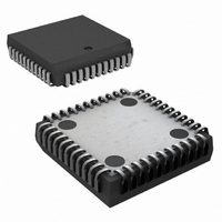
MM5452V/NOPB National Semiconductor, MM5452V/NOPB Datasheet - Page 6

MM5452V/NOPB
Manufacturer Part Number
MM5452V/NOPB
Description
IC DVR LCD 32 SEG DISPLAY 44PLCC
Manufacturer
National Semiconductor
Datasheet
1.MM5453VNOPB.pdf
(10 pages)
Specifications of MM5452V/NOPB
Display Type
LCD
Configuration
7 Segment + DP, Alphanumeric & Bar Graph
Interface
Serial
Digits Or Characters
4.5 Digits
Voltage - Supply
3 V ~ 10 V
Operating Temperature
-40°C ~ 85°C
Mounting Type
Surface Mount
Package / Case
44-PLCC
Operating Supply Voltage (typ)
3.3/5/9V
Number Of Digits
4.5
Number Of Segments
32
Operating Temperature (min)
-40C
Operating Temperature (max)
85C
Operating Temperature Classification
Industrial
Package Type
PLCC
Pin Count
44
Mounting
Surface Mount
Power Dissipation
350mW
Frequency (max)
1MHz
Operating Supply Voltage (min)
3V
Operating Supply Voltage (max)
10V
Lead Free Status / RoHS Status
Lead free / RoHS Compliant
Current - Supply
-
Lead Free Status / Rohs Status
Compliant
Other names
*MM5452V
*MM5452V/NOPB
MM5452V
*MM5452V/NOPB
MM5452V
Available stocks
Company
Part Number
Manufacturer
Quantity
Price
Company:
Part Number:
MM5452V/NOPB
Manufacturer:
Texas Instruments
Quantity:
10 000
www.national.com
*The minimum recommended value for R for the oscillator input is 9 kΩ. An RC time constant of approximately 4.91 × 10
between 30 Hz and 150 Hz.
Figure 7 shows a four wire remote display that takes advan-
tage of the device’s serial input to move many bits of display
information on a few wires.
USING AN EXTERNAL CLOCK
The MM5452/MM5453 LCD Drivers can be used with an ex-
ternally supplied clock, provided it has a duty cycle of 50%.
Deviations from a 50% duty cycle result in an offset voltage
on the LCD. In Figure 6, a flip-flop is used to assure a 50%
duty cycle. The oscillator input is grounded to prevent oscil-
lation and reduce current consumptions in the chips. The
oscillator is not used.
FIGURE 5. Parallel Backplane Outputs
FIGURE 6. External Backplane Clock
6
Using an external clock allows synchronizing the display drive
with AC power, internal clocks, or DVM integration time to re-
duce interference from the display.
Figure 8 is a general block diagram that shows how the
device’s serial input can be used to advantage in an analog
display. The analog voltage input is compared with a staircase
voltage generated by a counter and a digital-to-analog con-
verter or resistor array. The result of this comparison is
clocked into the MM5452, MM5453. The next clock pulse in-
crements the staircase and clocks the new data in.
−4
should produce a backplane frequency
613707
613708


