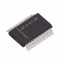
MAX1492CAI+T Maxim Integrated Products, MAX1492CAI+T Datasheet - Page 15

MAX1492CAI+T
Manufacturer Part Number
MAX1492CAI+T
Description
IC ADC W/LCD DRIVER 28-SSOP
Manufacturer
Maxim Integrated Products
Datasheet
1.MAX1494CCJ.pdf
(34 pages)
Specifications of MAX1492CAI+T
Display Type
LCD
Configuration
7 Segment + 2 Annunciators
Interface
Serial
Digits Or Characters
A/D 3.5 Digits
Current - Supply
960µA
Voltage - Supply
2.7 V ~ 5.25 V
Operating Temperature
0°C ~ 70°C
Mounting Type
Surface Mount
Package / Case
28-SSOP
Lead Free Status / RoHS Status
Lead free / RoHS Compliant
Figure 21 shows the MAX1492/MAX1494 operating with
an external single-ended reference. In this mode, REF-
is connected to GND and REF+ is driven with an exter-
nal 2.048V reference. Bypass REF+ to GND with a
0.47µF capacitor.
Figure 9. LCD Voltage Waveform—Combinations 1–4 (BP_, SEG2/5/8)
______________________________________________________________________________________
g, d OFF
a, d OFF
a, g OFF
g ON
d ON
a ON
BP1
BP2
BP3
OFF
ALL
3.5- and 4.5-Digit, Single-Chip ADCs
φ1, φ2, φ3 - - BP HIGH WITH RESPECT TO SEGMENT (BP+ TIME)
φ1', φ2', φ3' - - BP LOW WITH RESPECT TO SEGMENT (BP- TIME)
BP1 ACTIVE DURING φ1 AND φ1'
BP2 ACTIVE DURING φ2 AND φ2'
BP3 ACTIVE DURING φ3 AND φ3'
φ1
φ2
FREQUENCY = 107Hz
φ3
φ1'
Figure 20 shows the MAX1492/MAX1494 operating with
an external differential reference. In this mode, REF-
is connected to the top of the strain gauge and REF+
is connected to the midpoint of the resistor-divider of
the supply.
φ2'
φ3'
V+ = V
V
V
V
L
LCD
LCD
= 1/3 V
= V
= V
DVDD
DVDD
DVDD
LCD
, V
with LCD Drivers
, V- = GND OR V
H
- V
- V
= 2/3 V
DISP
GND
(MAX1492)
(MAX1494)
DVDD
V+
V
V
V-
V+
V
V
V-
V+
V
V
V-
V+
V
V
V-
V+
V
V
V-
V+
V
V
V-
V+
V
V
V-
H
L
H
L
H
L
H
L
H
L
H
L
H
L
DISP
V
LCD
15


