LM2412T/NOPB National Semiconductor, LM2412T/NOPB Datasheet - Page 6
LM2412T/NOPB
Manufacturer Part Number
LM2412T/NOPB
Description
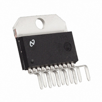
IC DRIVER MONOLITHIC TO-220-11
Manufacturer
National Semiconductor
Datasheet
1.LM2412TNOPB.pdf
(11 pages)
Specifications of LM2412T/NOPB
Display Type
CRT
Current - Supply
21mA
Voltage - Supply
60 V ~ 85 V
Operating Temperature
-20°C ~ 100°C
Mounting Type
Through Hole
Package / Case
TO-220-11 (Bent and Staggered Leads)
Lead Free Status / RoHS Status
Lead free / RoHS Compliant
Interface
-
Configuration
-
Digits Or Characters
-
Other names
*LM2412T
*LM2412T/NOPB
LM2412T
*LM2412T/NOPB
LM2412T


www.national.com
Application Hints
good example of a layout that can be used as a guide for
future layouts. Note the location of the following compo-
nents:
The routing of the LM2412 outputs to the CRT is very critical
to achieving optimum performance. Figure 13 shows the
routing and component placement from pin 1 to the blue
cathode. Note that the components are placed so that they
almost line up from the output pin of the LM2412 to the blue
cathode pin of the CRT connector. This is done to minimize
• C47 - V
• C49 - V
• C46 and C77 - V
and ground pins. ( Figure 12 )
ground. ( Figure 12 )
V
( Figure 11 )
CC
clamp diodes. Very important for arc protection.
BB
CC
bypass capacitor, located close to pin 10 and
bypass capacitor, located very close to pin 6
CC
bypass capacitors, near LM2412 and
(Continued)
6
the length of the video path between these two components.
The direct video path is shown in by a dark gray line through
the components and the PCB traces. Note also that D24,
D25, R58 and D19 are placed to keep the size of the video
nodes to a minimum (R58 is located under D19). This mini-
mizes parasitic capacitance in the video path and also en-
hances the effectiveness of the protection diodes. The traces
in the video nodes to these components are shown by the
white line. The anode of protection diode D25 is connected
directly to the ground plane giving a short and direct path to
the LM2412 ground pins. The cathode of D24 is connected
to V
which is connected to the same section of the ground plane
as D25. The diode placement and routing is very important
for minimizing the voltage stress on the LM2412 during an
arc-over event. Lastly, notice that S3 is placed very close to
the blue cathode and is tied directly to CRT ground.
CC
very close to decoupling capacitor C78 ( Figure 13 )
Related parts for LM2412T/NOPB
Image
Part Number
Description
Manufacturer
Datasheet
Request
R

Part Number:
Description:
Monolithic Triple 2.8 nsec Driver
Manufacturer:
National Semiconductor
Datasheet:
Part Number:
Description:
National Semiconductor [8-Bit D/A Converter]
Manufacturer:
National Semiconductor
Datasheet:
Part Number:
Description:
National Semiconductor [Media Coprocessor]
Manufacturer:
National Semiconductor
Datasheet:
Part Number:
Description:
Digitally Controlled Tone and Volume Circuit with Stereo Audio Power Amplifier, Microphone Preamp Stage and National 3D Sound
Manufacturer:
National Semiconductor
Datasheet:
Part Number:
Description:
Digitally Controlled Tone and Volume Circuit with Stereo Audio Power Amplifier, Microphone Preamp Stage and National 3D Sound
Manufacturer:
National Semiconductor
Datasheet:
Part Number:
Description:
AC97 Rev 2 Codec with Sample Rate Conversion and National 3D Sound
Manufacturer:
National Semiconductor
Part Number:
Description:
Manufacturer:
National Semiconductor
Datasheet:
Part Number:
Description:
Manufacturer:
National Semiconductor
Datasheet:
Part Number:
Description:
General Purpose, Low Voltage, Low Power, Rail-to-Rail Output Operational Amplifiers
Manufacturer:
National Semiconductor
Datasheet:
Part Number:
Description:
8-bit 20 MSPS flash A/D converter.
Manufacturer:
National Semiconductor
Datasheet:
Part Number:
Description:
Low Noise Quad Operational Amplifier
Manufacturer:
National Semiconductor
Datasheet:
Part Number:
Description:
Quad Differential Line Receivers
Manufacturer:
National Semiconductor
Datasheet:
Part Number:
Description:
Quad High Speed Trapezoidal? Bus Transceiver
Manufacturer:
National Semiconductor
Datasheet:
Part Number:
Description:
Dual Line Receiver
Manufacturer:
National Semiconductor
Datasheet: