FAN5608DHMPX Fairchild Semiconductor, FAN5608DHMPX Datasheet
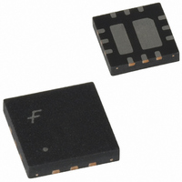
IC LED DRIVR WHITE BCKLGT 12-MLP

FAN5608DHMPX

Manufacturer Part Number
FAN5608DHMPX
Description
IC LED DRIVR WHITE BCKLGT 12-MLP
Manufacturer
Fairchild Semiconductor
Type
Backlight, White LED (Serial Interface)r
Datasheet

Specifications of FAN5608DHMPX

Topology
PWM, Step-Up (Boost)
Number Of Outputs
2
Internal Driver
Yes
Type - Primary
Backlight
Type - Secondary
White LED
Frequency
500kHz
Voltage - Supply
2.7 V ~ 5.5 V
Voltage - Output
24V
Mounting Type
Surface Mount
Package / Case
12-MLP
Operating Temperature
-40°C ~ 85°C
Current - Output / Channel
20mA
Internal Switch(s)
Yes
Efficiency
85%
Number Of Segments
12
Operating Supply Voltage
2.7 V to 5.5 V
Maximum Supply Current
20 mA
Maximum Operating Temperature
+ 85 C
Mounting Style
SMD/SMT
Minimum Operating Temperature
- 40 C
Lead Free Status / RoHS Status
Lead free / RoHS Compliant
Other names
FAN5608DHMPXTR
FAN5608DHMPX_NL
FAN5608DHMPX_NLTR
FAN5608DHMPX_NLTR

Available stocks

Company
Part Number
Manufacturer
Quantity
Price
Part Number:
FAN5608DHMPX
Manufacturer:
FAIRCHILD/仙童
Quantity:
20 000
Company:
Part Number:
FAN5608DHMPX
Quantity:
1 700
Features
• Two Independent Channels Drive up to Six LEDs per
• Adaptive Output Voltage Drive to Maximize Efficiency
• PWM/PFM Mode of Operation of the boost circuit
• Up to 85% Efficiency
• Up to
• Two Built-in DACs for Independent (Digital) Brightness
• LED’s Current Can be Duty-Cycle-Modulated between
• Digital, analog, and PWM brightness control
• 2.7V to 5V Input Voltage Range
• 0.5MHz Operating Frequency (8MHz internal clock)
• Soft Start
• Low Shutdown Current: I
• LED Short Circuit Protection
• Minimal External Components Needed
• Available in an 8-lead MLP and a 12-lead MLP Package
Applications
• Cell Phones
• Handheld Computers
• PDAs, DSCs, MP3 Players
• Keyboard Backlights
• LED Displays
FAN5608
Serial/Parallel LED Driver with Current-Regulated,
Step-Up DC/DC Converter
Typical Application
Channel
Control for Both Channels
0 to 20mA
DAC Input For CH1
DAC Input For CH2
2.7V to 5V
2
20mA
L = 4.7 H
4X4mm MLP-12 Package
with internal Schottky diode
Order Code: FAN5608DHMPX
Output
B2
IND
V
A1
B1
A2
IN
CC
< 1
µ
V
GND
IND
CH2
CH1
NC
OUT
NN
A
4.7µF
Analog or Digital Brightness Control
V
OUT
Description
The FAN5608 LED driver generates regulated output cur-
rents from a battery with input voltage varying between 2.7V
to 5V. An internal NMOS switch drives an external inductor,
and a Schottky diode delivers the inductor’s stored energy to
the load. Proprietary internal circuitry continuously monitors
each LED current string and automatically adjusts the gener-
ated output DC voltage to the lowest minimum value
required by the LED’s string with the highest summarized
forward voltage. This adaptive nature of the FAN5608
ensures operation at the highest possible efficiency. Soft start
circuitry prevents excessive current drawn from the supply
during power on. Any number of LEDs can be connected in
series as long as the summed forward voltages do not lead to
exceeding the specified operating output voltage range.
Although it is not required to have an equal number of LEDs
connected in series within each branch, the highest efficiency
and best current regulation is always achieved when an equal
number of LEDs are serially connected.
In the FAN5608 device, two internal two-bit D/A converters
provide independent programmability of each output channel
current. Analog programming of the output current is also
possible in the FAN5608. To do this, ground the "B" pins and
connect a resistor between the "A" pins and a fixed supply
DAC Input For CH1
DAC Input For CH2
2.7V to 5V
L = 4.7 H
4X4mm MLP-12 Package
with external Schottky diode
Order Code: FAN5608HMPX
B2
IND
V
A1
B1
A2
IN
www.fairchildsemi.com
GND
IND
CH2
CH1
NC
NC
4.7µF
REV. 0.8.3 5/29/03
V
OUT

Related parts for FAN5608DHMPX

FAN5608DHMPX Summary of contents

Page 1

... 4X4mm MLP-12 Package with internal Schottky diode Order Code: FAN5608DHMPX Description The FAN5608 LED driver generates regulated output cur- rents from a battery with input voltage varying between 2.7V to 5V. An internal NMOS switch drives an external inductor, and a Schottky diode delivers the inductor’s stored energy to the load ...

Page 2

... Although this definition leads to a lower value than the boost converter efficiency, it more accurately reflects better system per- formance, from the user’s point-of-view. 2 8-lead MLP package with or without an internal Schottky specified range. The diode. The FAN5608DHMPX is available in a 12-lead MLP package with an internal Schottky diode. Analog Brightness Control 4.7µF I measured I OUT ...

Page 3

... IN IN CH1 GND CH2 3 6 CH2 IND IND 4 OUT 3x3mm 8-Lead MLP 3x3mm 8-Lead MLP (Internal Schottky Diode) (External Schottky Diode) FAN5608DMPX/FAN5608MPX Pin Descriptions Pin No. FAN5608DHMPX FAN5608HMPX 1 GND 2 CH1 CH2 9 IND 10 IND 11 V OUT 12 NC REV. 0.8.3 5/29/03 TOP-VIEW A1 8 CH1 ...

Page 4

... Using Mil Std. 883E, method 3015.7(Human Body Model) and EIA/JESD22C101-A (Charge Device Model). 2. Avoid positive polarity ESD stress at the cathode of the internal Schottky diode. 4 Conditions A = HIGH HIGH A = HIGH HIGH V > 3.0V IN FAN5608DMPX/ FAN5608MPX FAN5608DHMPX/ FAN5608HMPX Digital High Mode Low Analog Mode Digital Mode High ...

Page 5

Preliminary Data Sheet Block Diagram DAC1 A1 B2 DAC2 A2 GND Note: In the 8-pin version (analog version only), pins B1 and B2 are omitted. Circuit Description When the input voltage is connected to V turned on, ...

Page 6

Preliminary Data Sheet Digital Control The FAN5608’s digital decoder allows selection of the fol- lowing modes of operation: OFF, 5mA, 10mA, 20mA per branch OFF 5mA 10mA LED Analog Control with ...

Page 7

Preliminary Data Sheet PWM Control (Continued High and B is PWM. I LED A Input B Input (PWM) I LED 0mA 3. A and B are PWM. I (Average) = LED A Input (PWM) B Input (PWM) ...

Page 8

FAN5608 Applications Information Inductor Selection The inductor is one of the main components required by the boost converter to store energy. The amount of energy stored in the inductor and transferred to the load is controlled by the regulator using ...

Page 9

Preliminary Data Sheet Application Examples 1. Driver For Four White LEDs L = 6 IND IND V V OUT IN A1 GND DAC Input For CH1 B1 CH2 A2 CH1 DAC Input For CH2 NN B2 ...

Page 10

FAN5608 4. Driver For Twelve White LEDs L = 4 IND IND V V OUT IN A1 GND DAC Input For CH1 B1 CH2 A2 CH1 DAC Input For CH2 Note: Refer to ...

Page 11

Preliminary Data Sheet Mechanical Dimensions 4x4mm 12-Lead MLP (Internal Schottky Diode) REV. 0.8.3 5/29/03 GND V OUT FAN5608 11 ...

Page 12

FAN5608 Mechanical Dimensions 4x4mm 12-Lead MLP (External Schottky Diode) 12 Preliminary Data Sheet REV. 0.8.3 5/29/03 ...

Page 13

Preliminary Data Sheet Mechanical Dimensions 3x3mm 8-Lead MLP (Internal Schottky Diode) REV. 0.8.3 5/29/03 V OUT GND FAN5608 13 ...

Page 14

FAN5608 Mechanical Dimensions 3x3mm 8-Lead MLP (External Schottky Diode) 14 Preliminary Data Sheet REV. 0.8.3 5/29/03 ...

Page 15

... Schottky Diode Internal FAN5608DHMPX External Internal External 2. A critical component in any component of a life support device or system whose failure to perform can be reasonably expected to cause the failure of the life support device or system affect its safety or effectiveness ...

Related keywords