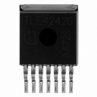
TLE4242G Infineon Technologies, TLE4242G Datasheet

TLE4242G
Specifications of TLE4242G
SP000299340
TLE4242GINTR
TLE4242GNT
TLE4242GT
TLE4242GT
TLE4242GXT
Available stocks
Related parts for TLE4242G
TLE4242G Summary of contents
Page 1
Adjustable LED Driver Features • Adjustable constant current up to 500 mA (±5%) • Wide input voltage range • Low drop voltage • Open load detection • Overtemperature protection • Short circuit proof • Reverse polarity ...
Page 2
Circuit Description 1 I Bias Supply 2 PWM Bandgap Reference Figure 1 Block Diagram An external shunt resistor in the ground path of the connected LEDs is used to sense the LED current. A regulation loop helds the voltage drop ...
Page 3
Figure 2 Pin Configuration (top view) Table 1 Pin Definitions and Functions Pin No. Symbol PWM GND 5 REF Data Sheet REF PWM GND D AEP01938_4242 ...
Page 4
Application Information V I BAT TLE 4269 G RADJ GND Figure 3 Application Circuit Figure 3 shows a typical application with the TLE 4242 G LED driver. The 3 LEDs are driven with an adequate supply current adjusted by the ...
Page 5
The functionality of the ST and PWM as well as their timings are shown in Status delay can be adjusted via the capacitor connected to the timing Pin D. The delay time scales in linear way with the capacitance C ...
Page 6
Table 2 Absolute Maximum Ratings -40 °C < < 150 ° Parameter Input Voltage Current Output Voltage Current Status Output Voltage Current Status Delay Voltage Reference Input Voltage Current Pulse Width Modulation Input Voltage Current Temperatures Junction temperature ...
Page 7
Table 3 Operating Range Parameter Input voltage Status output voltage Status Delay capacitance PWM voltage Junction temperature Reference resistor Data Sheet Symbol Limit Values Min. Max – 2 ...
Page 8
Table 4 Electrical Characteristics = 0.47 Ω 13 REF to ground; positive current defined flowing into pin; unless otherwise specified Parameter Symbol I Current consumption qOFF off mode I Current consumption qL Output I Output ...
Page 9
Table 4 Electrical Characteristics (cont’d) = 0.47 Ω 13 REF to ground; positive current defined flowing into pin; unless otherwise specified Parameter Symbol Reference V Reference Voltage REF I Reference Input REF Current Status Output ...
Page 10
Typical Performance Characteristics Output Current versus External Resistor ...
Page 11
PWM Pin Input Current versus PWM Voltage Data Sheet PWM Pin Input Current ...
Page 12
Package Outlines 7x0.6 ±0.1 1) Typical All metal surfaces tin plated, except area of cut. Figure 5 PG-TO263-7-1 (Plastic Transistor Single Outline) Green Product (RoHS compliant) To meet the world-wide customer requirements for environmentally friendly products and to be compliant ...
Page 13
Version Date Rev. 1.0 2004-01-01 Initial version Rev. 1.1 2007-03-20 Initial version of RoHS-compliant derivate of TLE 4242 G Data Sheet Changes Page 1: AEC certified statement added Page 1 and Page 12: RoHS compliance statement and Green product feature ...
Page 14
... Infineon Technologies Office. Infineon Technologies components may be used in life-support devices or systems only with the express written approval of Infineon Technologies failure of such components can reasonably be expected to cause the failure of that life-support device or system or to affect the safety or effectiveness of that device or system. Life support devices or systems are intended to be implanted in the human body or to support and/or maintain and sustain and/or protect human life ...


